Ambient Lighting From Video
This tutorial explores a method to ambiently light an area behind or surrounding a video display based on the colors and intensity in the video shown on that display. The included example uses four RGB lighting fixtures (or groups of RGB fixtures), which are controlled by color sampling each quadrant of the content being sent to the display. Also included in the download is a 3D model of the lighting setup so that you can view and fine-tune the effects without actual lighting fixtures. These effects are achieved by using QLab in conjunction with a program called Vuo.
What is Vuo
Vuo is a visual programming environment, not that dissimilar to the now deprecated Quartz Composer but with far more features. You program it by adding nodes to a composition and connecting them. You can then export the compositions as stand-alone apps.
Vuo can receive, analyze, process, generate, and transmit audio and video through core Apple technologies, as well as through Syphon, NDI, and Blackmagic Designs hardware. It can send and receive MIDI, OSC, Art-Net, and RS232 to interface with other software and hardware.
Vuo is developed by Kosada in Athens, Ohio, US. There is a free version, available for personal use and for some qualifying small businesses and professionals. The free version has a slightly limited feature set. The paid version has all the features enabled and a license for commercial use. You can find out more about Vuo, and download it at vuo.org.
QLab and Vuo
When used with QLab, Vuo is a veritable Swiss Army knife of apps! It handles almost every type of media and data that QLab can send or receive. If you have an idea that can’t be achieved entirely within QLab, it’s often possible to come up with a working solution using QLab and Vuo in a few hours. Here are some examples of how you might extend QLab’s capabilities using Vuo.
- Video FX beyond those included in QLab
- Touch screen overlays for QLab that can control QLab using OSC, for kiosk and museum use
- Video frame stores, delays, and recorders
- Spherical projection for planetarium-style projection
- Stopwatches, clocks, and information displays, including the display of QLab status information
- On-screen controllers outputting MIDI and OSC
- Face detection and tracking
- Color sampling of video feeds
- Custom Syphon and NDI viewers
The example project used in this tutorial is an ideal demonstration of some of these capabilities. Vuo receives video from QLab using Syphon; it color samples the video and converts these colors to RGB values; it displays these values in a virtual 3D model in a Vuo window, and simultaneously sends the values back to QLab as OSC messages which remote-control the Light Dashboard. The conversion can be fine tuned using MIDI feedback from a custom fixture in QLab’s lighting dashboard. This version only uses nodes included in the free version of Vuo.
Here it is in action:
On the left side of the video is QLab’s Light Dashboard. There are four generic RGB instruments and one custom instrument created especially to control the Vuo composition. This custom fixture doesn’t correspond to an actual lighting fixture; it’s used to fine-tune the video before it is color sampled. The .color virtual parameter of instrument 2 is shown selected, so that the color control (the triangle in the sidebar) displays the current color of that instrument.
At the bottom right of the video is Vuo’s output display. This shows the video content being playing in QLab on top of a 3D model simulating the appearance of a physical projection screen or LED wall in front of a cyclorama or other scenic element being softly lit by four RGB lighting fixtures.
Cue “VUO” in QLab’s cue list is set in Workspace Settings → General to start automatically when the workspace is opened.
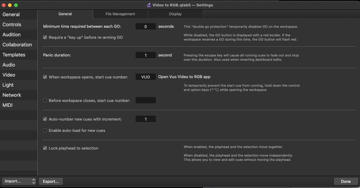
Cue “VUO” is a Script cue with the following script:
tell application "Video to RGB" to activate
delay 1
tell application id "com.figure53.QLab.5" to tell front workspace
  activate
  set theDashboard to current light dashboard
  tell theDashboard to clear
  delay 0.5
  start cue "DEF"
  set the playback position of front cue list to cue "1"
end tell
This opens the app that will perform the video to RGB transformation, clears QLab’s dashboard (which resets all parameters of all instruments to their home values), starts cue “DEF”, which sets the app’s parameters to the default settings, and sets the playhead to cue “1”.
Cue “DEF” has a hotkey trigger, ⇧D, to enable the default parameters to be easily recalled at any time.
Cue “1” is a four color test card which clearly shows how the ambient lighting is derived from the four quadrants of the video image.
Cues “2” through “6” show a variety of still and moving Video cues which demonstrate how the ambience lighting reacts.
Cues “7” and “8” are Video cues grouped with a Light cue. These Light cues adjust ambience parameters to optimize the ambiance analysis for those specific videos. The video shows these parameters being adjusted, with results visible in real-time, and then the adjusted parameters are saved to the Light cue in the Group.
Cue “9” returns the ambience parameters to default and displays the test card once again.
How it works
QLab lighting setup
In Workspace Settings → Light → Light Patch, we add four instruments using the “Generic RGB Fixture” instrument definition, and auto-patch them using Art-net.
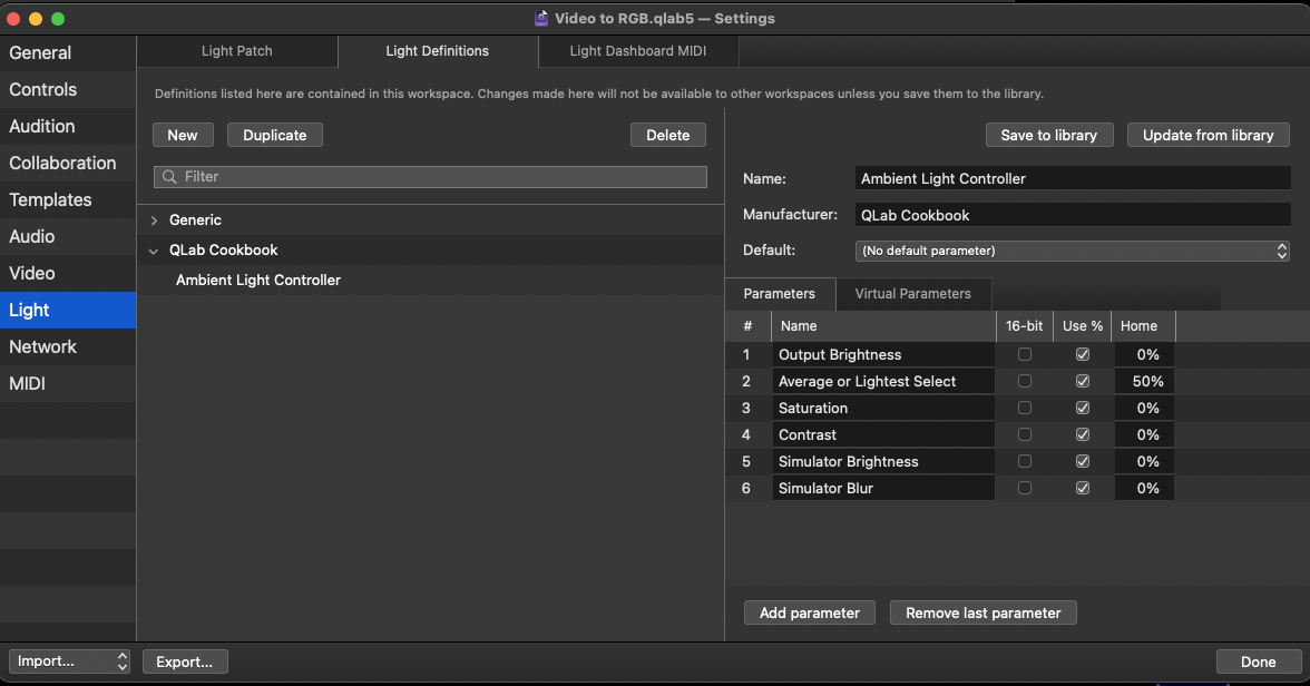
Next, we move to the Light Definitions tabs and create a new instrument definition named “Ambient Light Controller.”
Set the manufacturer to a name of your choosing so you can easily locate it later. The example uses “QLab Cookbook”.
Add six parameters named and configured according the screenshot below.
When you hit Done the definition will be saved within the workspace. If you would like to use this instrument definition in other workspaces, you can click Save to library which will save the definition to the light library on your Mac. Lights in the library are available to all workspaces on your Mac.
Return to the Light Patch tab and add a new instrument to the patch using the new instrument definition we just created. You will find it in the pop-up menu, listed under the Workspace Library, and also listed under the manufacturer’s heading for QLab Cookbook.
Name the new instrument “Ambience”. Auto-patch it to an unused Art-net universe; the example uses universe 10. We won’t actually be using the DMX output of this instrument, only the MIDI output from the Light Dashboard. Processing MIDI data is much easier than processing Art-net frames.
Move to the Light Dashboard MIDI tab and set Send MIDI feedback to IAC Bus 1 on channel 11. This must be a different channel than the Light MIDI channel (channel 1 in the screen shot.)
In the table below, select each of the parameters of the Ambience instrument and create a binding using Control Change and the controller number in the screenshot.
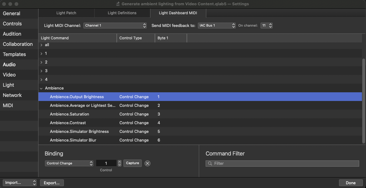
Now, whenever a dashboard slider for the Ambiance instrument is set to a new level, that change will be sent as MIDI data to Vuo.
QLab video setup
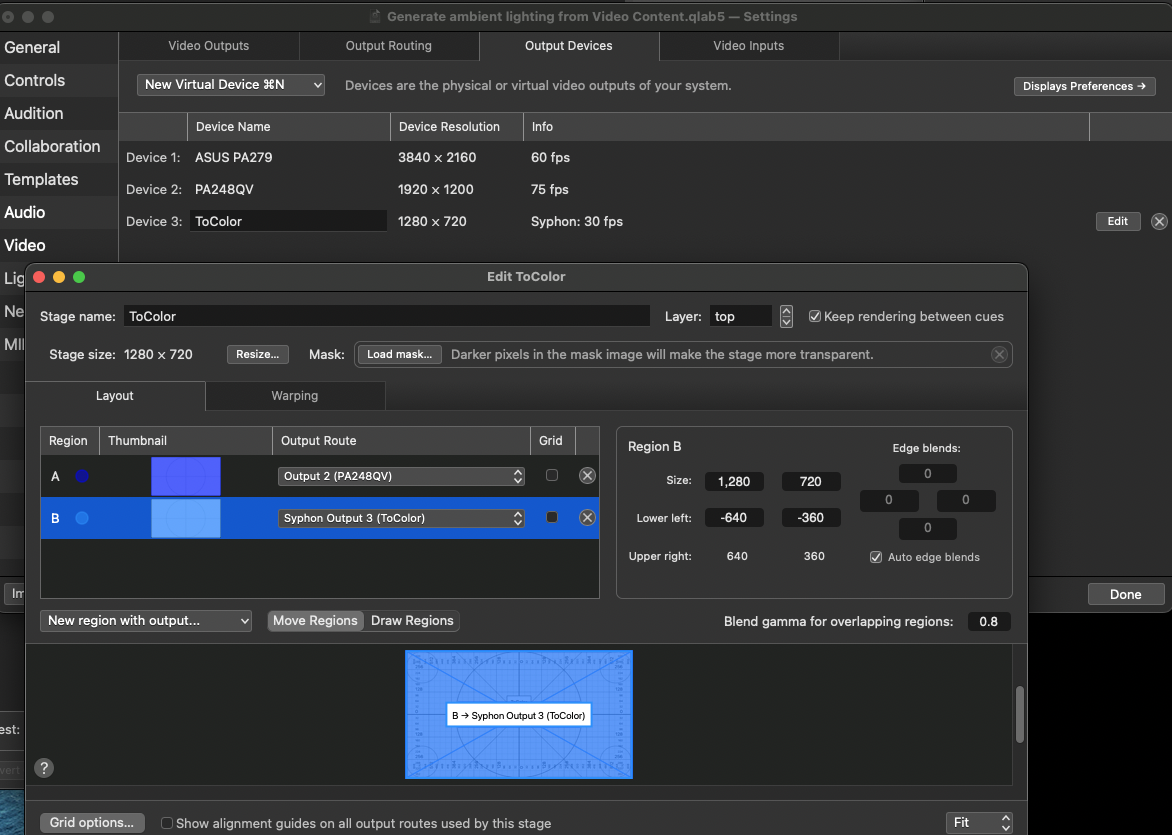
In Workspace Settings → Video → Output Devices, we need to create a new Syphon device and name it “ToColor”. This is only used by Vuo for sampling, so a resolution of 1280 × 720 at 30 fps will be fine.
In Video Outputs, edit the stage that will send to your projection screen or LED wall. Add a “New Region with Output” using the pop-up menu and select the “ToColor” Syphon output device.
Vuo setup
The Vuo composition looks like this:
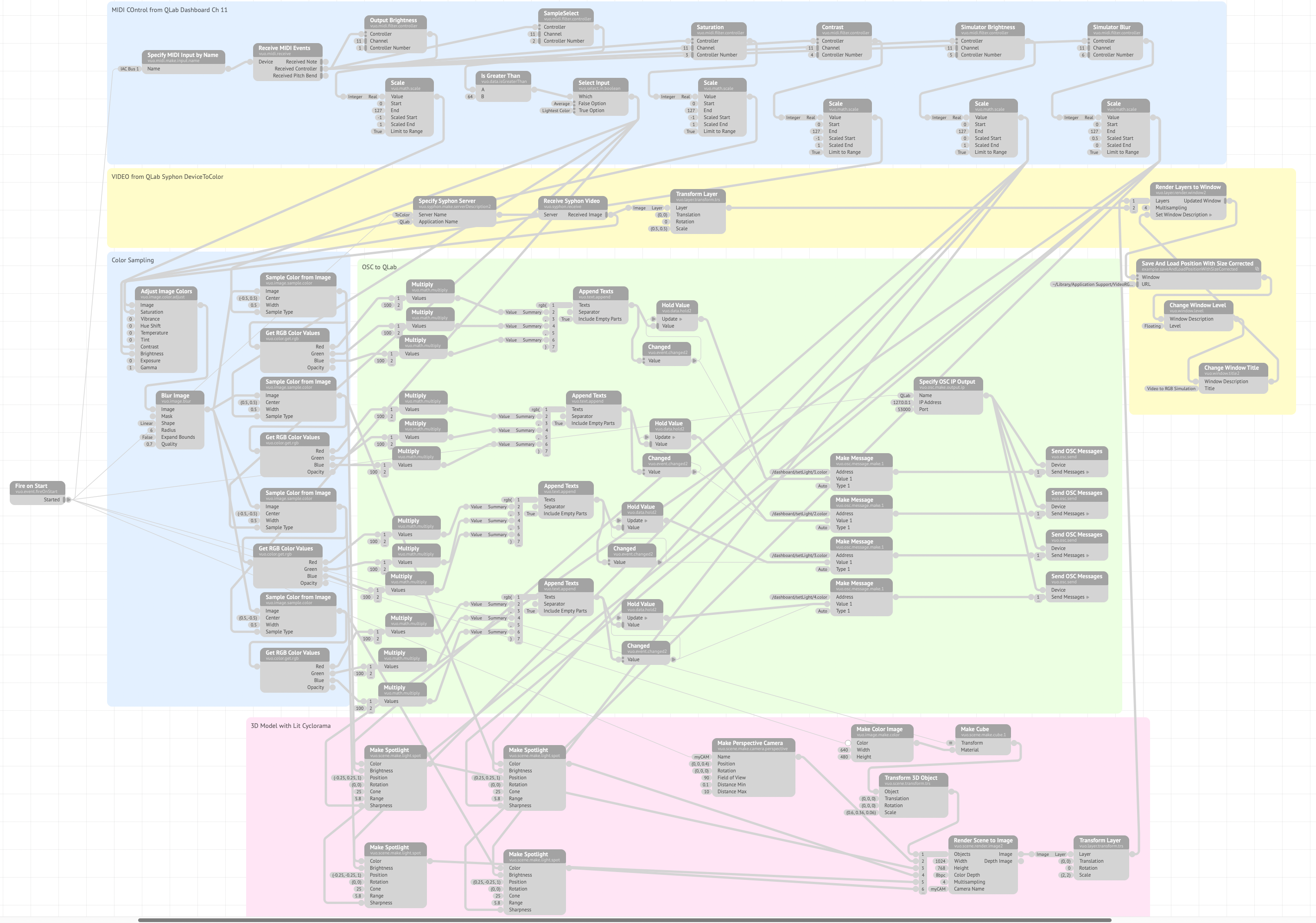
On the left of the composition is a Fire On Start node. This sends an event when the composition is started. Most of the nodes in the composition will fire automatically when frames of video are passed through the nodes, but some are outside the video flow, such as nodes that specify a device like Specify OSC IP Output. The Fire on Start node is connected to these nodes so that they trigger when the composition is started.
The blue section labeled MIDI control from QLab Dashboard Ch 11, has nodes that:
- Specify the MIDI Input by Name to tell Vuo what MIDI Input to listen to.
- Receive MIDI Events which pass all the controller data to six Filter Controller Nodes, each labeled with its function. All six nodes listen for MIDI data on channel 11 only.
- The Output Brightness filter listens for messages with controller number 1, and uses a Scale node to scale its output to a range of -1 to 1.
- The Saturation filter listens for messages with controller number 3, and uses a Scale node to scale its output to a range of -1 to 1.
- The Contrast filter listens for messages with controller number 4, and uses a Scale node to scale its output to a range of -1 to 1.
- The Simulator Brightness filter listens for messages with controller number 5, and uses a Scale mode to scale its output to a range of 0 to 1.
- The Simulator Blur filter listens for messages with controller number 6, and uses a Scale node to scale its output to a range of 0.5 to 0. This scale goes from large to small because this data will be sent to a sharpness control which uses 0 for soft and 1 for hard.
- The Sample Select listens for messages with controller number 2 and then uses a Is Greater Than node to determines if the value is greater than 64. This controls a boolean Select Input node which switches between average and lightest color sampling. This lets you choose which type of color sampling you want to use by setting the corresponding slider in the Light Dashboard to below 50% or above 50%. It’s probably simplest to just use 0% and 100%.
The yellow section labeled VIDEO from QLab Syphon DeviceToColor uses a Specify Syphon Server node to tell the composition which Syphon server to pull video from. In the example, this is named “ToColor”. This node connects to a Receive Syphon Video node to receive the video frames, and then to a Transform Layer node to send these frames directly to the front layer (layer 2) of a Render Layers To Window node, and also to the nodes in the “Color Sampling” section.
In the blue section labeled Color Sampling, the video arrives at the Adjust Image Colors node. The values for the parameters we are adjusting (Saturation, Contrast and Brightness), are received from the blue MIDI control section above.
The video then passes to a Blur Image node which applies a small linear blur,.
From there, the video is spit to four Sample Color From Image nodes. Each of these nodes has its ‘center’ and ‘width’ controls set to sample one of the quadrants of the video image. The ‘sample type’ for all four nodes gets its value from the Select Input node in the blue MIDI control section above.This value sets the sample type to either “average” or “lightest color”.
Each of the four nodes outputs a color which is passed to a Get RGB Color Values node to output numerical values for red, green, and blue, normalized to a range of 0 to 1.
In the green section labeled OSC to QLab, the RGB values for each quadrant are all multiplied by 100 (Multiply node) to get the percentage value QLab requires, and formatted into a text message (Append Texts node) formatted the way QLab wants it, i.e. rgb({r},{g},{b}).` These values are sent to Hold Value nodes. When a value changes, the Changed node sends an event to the update port of the Hold Value node, which then transmits its stored value.
This is received by a Make Message node, where it becomes the argument to an OSC message set in the address port of the node. So, if instrument 1 is to be set to red, the Make Message node assembles the complete OSC message:
/dashboard/setLight/1.color rgb(100,0,0)
This is immediately sent by a Send OSC Messages node to the IP address and port specified by the Specify OSC IP Output node. Since we are sending OSC to QLab running on the same computer, we use 127.0.0.1 port 53000. If you’ve set your workspace to use a different port for incoming OSC, you’ll need to modify the port number here as well.
In order to see the video with a simulation of the RGB lighting, we create a 3D model of a cyclorama lit with four spotlights in the pink section labeled 3D Model with Lit Cyclorama.
Four Make Spotlight nodes receive their color from the color sample nodes, their brightness from the Simulator Brightness nodes and their sharpness from the Simulator Blur nodes. The purpose of the brightness and sharpness adjustment is to adjust the simulation to match the brightness and blending of actual RGB fixtures in reality.
The 3D model is completed by a Make Cube node dimensioned to represent a white cyclorama.
The scene is rendered to an image using a Make Perspective Camera node and a Render Scene to Image node, then scaled and combined with the clean video image as the background layer (layer 1) in the Render Layers to Window node.
Video content and photographs included in workspace © Mic Pool 2023. All rights reserved.
Vuo Composition by Mic Pool. Distributed under a CC BY-SA 4.0 DEED Attribution-ShareAlike 4.0 International License.