Audio is the heart of QLab.
Audio can come into QLab from an audio file, an audio track within a video file, a live input on an audio device connected to your Mac, or the audio track within an incoming NDI stream.
Audio can go out from QLab using the built-in speakers or headphone jack on your Mac, any macOS-compatible1 audio interface (usually connected via USB or Thunderbolt), or network-based audio output systems like Dante, AVB, and NDI.
Note: Timecode cues set to LTC output also generate audio in the form of an LTC signal from scratch. Since LTC is not meant to be a signal that human beings listen to, at least not on purpose, it's treated rather differently in QLab. Therefore, this section of the manual does not apply to Timecode cues which you can learn more about from the Timecode cue section of this manual.
Audio cues and Video cues generate output by reading audio from an audio file such as an AIFF, WAV, or other compatible file type, or by reading audio data from a compatible video file.
Mic cues and Camera cues generate output by reading audio from a live audio input such as a microphone or line input connected to your Mac's audio interface, or from audio contained in an NDI stream.
Once inside QLab, audio is treated more or less the same way no matter how it arrived.
Each cue that generates audio has a cue matrix mixer, which is unique to that cue and can be found in the Audio Levels tab of the inspector. The cue matrix mixer routes audio from the cue to the patch matrix mixer of the audio output patch that the cue is using. The patch matrix mixer, in turn, routes audio to the outputs of the audio device that the patch is using.
A matrix mixer is a mixer in which the signal from each input can be sent to each output at an individually set level. You can visualize a matrix mixer as a set of rows and columns. In QLab, each row represents an input, and each column represents an output. The intersection of each row and column is called a crosspoint; the point at which the row and column cross each other. Crosspoints are effectively volume knobs which control how much signal flows from the row into the column.
The matrix mixers in QLab consist of four sets of controls:
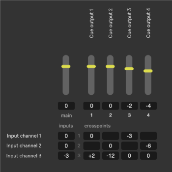
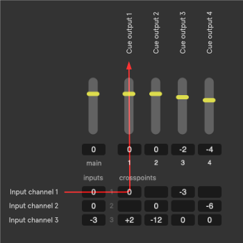
These images show a close-up view of the cue matrix mixer in QLab (with some additional annotations). The top row, row 0, contains the output level controls. Each successive row represents an input with audio entering the mixer on the left edge and flowing to the right.
The left-most column, column 0, contains in the input level controls. Each successive column represents a cue output with audio entering each output via the crosspoints in the middle of the matrix and flowing upwards to the output level controls.
In the top left corner, at row 0/column 0, is the main level control which sets the overall level for the whole cue.
In this example, the cue has three input channels routed to four cue outputs. If the cue is an Audio or Video cue, the inputs represent channels of audio in the target file. If the cue is a Mic cue or Camera cue, the inputs represent input channels on the source audio device.
In QLab, like most digital audio environments, a level of 0 represents unity gain which means "this level control makes no change in level." Whatever level comes in is the level that goes out. Therefore, we see that input channel 1 is routed to cue output 1 with no change in level, because the input, crosspoint, and output level controls for that signal path are all set to 0 dB. If input channel 1 is a recording of test tone that measures, say, -14 dB in the audio file, then a measurement of cue output 1 would also be -14 dB assuming no other sound was being played.
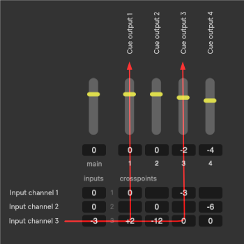
The whole point of the matrix, however, is that every level control can be set to any value. Input channel 3, for example, is set to -3 dB at the input, meaning its overall level is 3 dB quieter than the level recorded in the file. The crosspoint at the intersection of input 1 and output 1 is set to +2 dB, so the sum total level of input 3 in cue output 1 is -3 + 2 or -1 dB in cue output 1.
Input channel 3 is also routed to cue output 3, with the crosspoint at unity. Cue output 3's output level is set to -2 dB, however, so the sum total level of input 3 in cue output 3 is -3 + -2 or -5 dB in cue output 3.
Much of the time, particularly with smaller sound systems, this flexibility is not necessary and level adjustments to cues can be done largely with the main level control alone. When you need to get more exact, however, the full flexibility of the matrix mixer is there for you.
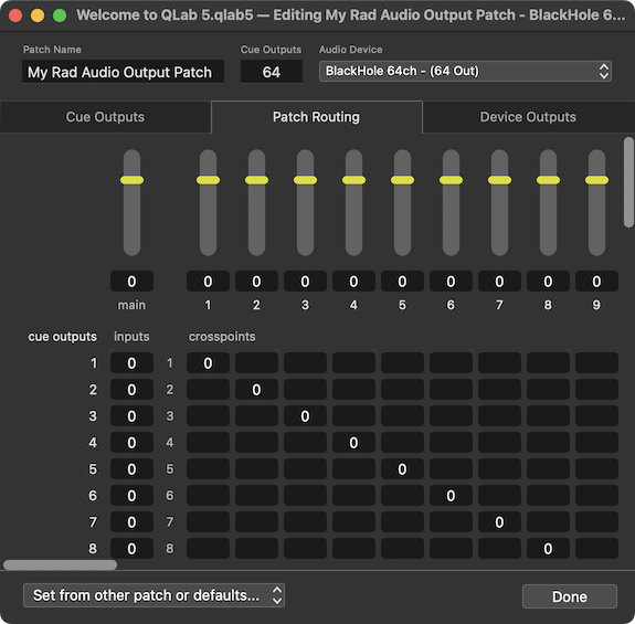

In the patch matrix mixer, each row represents the cue outputs from the cue matrix mixer. All the audio from all the cues is summed together and feeds into this matrix from the left side. The columns represent the device outputs, the outputs that are offered by your audio interface.
In these images, the audio patch is using a virtual audio device called Dante Virtual Soundcard which has 64 output channels, but to keep this discussion simpler we'll only consider the first eight outputs. The first image shows each cue output routed to a single device output at unity gain, so each cue output is effectively a direct path to one corresponding device output.
This is a great way to start working with a multichannel sound system in QLab, but it's certainly not the only way. For example, imagine this assignment of device outputs:
In this situation, device outputs 7 and 8 are feeding speakers that cover a section of audience that cannot hear the main speakers fed by outputs 1, 2, and 3. It might be nice if those outputs could automatically receive an appropriate mix if the signals being sent to those other device outputs, and voila, that is possible!
The second image shows cue output 1 routed to device output 1 at unity, and also routed to device output 7 at -3 dB (assuming that the front fills need a bit less oomph than the mains.) Cue output 2 repeats this with cue output 8. Cue output 3 routes to both 7 and 8 at -6 dB to reinforce the center channel.
You can learn more about the capabilities of audio output patches from the section on the Audio Output Patch Editor in this manual.
While levels in QLab are of course measured in decibels, it's important to understand that QLab necessarily uses dBFS (decibels relative to full scale) and not dB SPL (decibels of sound pressure level). QLab cannot know the absolute loudness of a sound for a number of reasons, but the simplest one is that QLab cannot know about the hardware that is being used beyond QLab. You might be playing QLab into a pair of tiny headphones, or you might be plugged into a million-watt sound system.
When a control is set to a level of 0 dB inside QLab, it simply means that the signal entering that control will be the same level when it leaves. If the control is set to -3 dB then the signal exits the control 3 dB quieter than it entered. That difference of -3, however, might translate into a larger or smaller difference depending upon the rest of the sound system.
In the most technical sense, what QLab knows as the device outputs are not necessarily the actual outputs of the audio device. Device manufacturers are responsible for creating the software drivers for their devices, which tell the Mac about the outputs and other capabilities of the hardware. The Mac, in turn, tells QLab. So, the device might have its own internal routing or other special features which could make for a discrepancy between what QLab sees and what's really there. For example, the iConnectivity device in the images above is listed as having eight outputs, but some of those outputs do not correspond to physical connections on the outside of the device. That's something that QLab cannot know.
By and large, any devices we've seen that do things like this are well designed and documented, so all that's needed to get the full picture is to read the manual for your audio interface and make sure you understand what's going on. If you find yourself having trouble, we encourage you to contact the manufacturer of the device before reaching out to us.
If the audio interface has a software control panel or virtual mixer interface, that control panel or mixer acts as a final post-QLab set of controls for the hardware.
The simplest example of this is the headphone jack on your Mac, which has volume controls on the keyboard and in the menu bar. These volume controls come "after" QLab, and therefore behave as an ultimate arbiter of the overall output volume. Other audio interfaces use other software controls, but the principle is the same.
Because QLab is designed for a live playback environment, in which different things may happen at different times and each performance of the same workspace may be slightly different, QLab uses an elastic approach to synchronization which is a bit unusual when compared to other audiovisual software. The end goal of this approach is to allow you to not think about sync at all if you don't want to worry about it, and to allow you to get specific, predictable behavior if you do want to worry about it.
If you do not want to worry about it, feel free to skip over this section.
If you do want to worry about it, there are two guidelines to remember when working on your cues:
Since there are two guidelines with two possible conditions each, there are four possible cases:
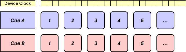
In this example, Cue A and Cue B are both assigned to the same audio output patch and both started simultaneously, either because they are both contained within a Timeline Group with identical pre-wait times, or because the first cue is set to auto-continue with no post-wait and the second cue, which is started via the auto-follow, has no pre-wait.
The simultaneous start causes the first sample from each cue to be played at the same time, and the clock of the audio device guarantees that samples from each cue will be played at the same cadence. As a result, the cues will start at the same time, and stay in sync for as long as they both run.
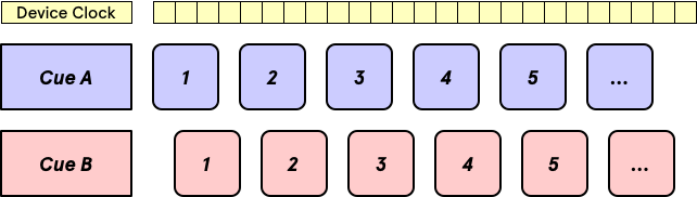
In this example, Cue A and Cue B are both assigned to the same audio output patch but they are not started simultaneously. This could be because one of them has a pre-wait; wait times use the system clock, not the audio device clock, and so wait times and audio playback cannot be perfectly synchronized. It could also be because they are not connected at all, and are started by two separate presses of the button, or one is started via the button and the other is started by a MIDI trigger or something else like that.
Because the start is not simultaneous, the first sample of each cue is played at a different time, but because both cues are still assigned to the same audio output patch the audio device clock still guarantees that samples from each cue are played at the same cadence. As a result, the two cues will remain in sync for as long as they both run, offset by the exact same amount of time throughout.
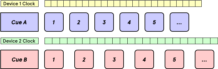
In this example, Cue A and Cue B are assigned to different audio output patch and both started simultaneously.
The start is simultaneous, so the first sample of each cue is played at the same time. Since the two audio output patches use different audio device clocks, though, the time between samples is different for the two cues. As a result, they will not remain in sync and will drift apart over time. The longer the cues are, the more audible the difference will become.
If sync is needed in this situation, using audio devices that have word clock connections can solve the problem by provided an external mechanism to sync the two clocks, thus converting this scenario into a "in sync and simultaneous" scenario.
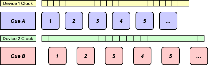
In this example, Cue A and Cue B are assigned to different audio output patch and not started simultaneously.
As a result, the first sample of each cue is played at a different time, and the cadence of each cue is different because they follow different clocks. These two cues have basically nothing to do with each other.
Most technically, an audio interface needs to be Core Audio compliant to work with QLab. There are some audio interfaces that work with Macs in general, but only with specific software. Those devices are in the tiny minority however. If an audio interface appears in the Sound section of System Preferences, it will almost definitely work with QLab. ↩
This can be changed for Video cues, but don't worry about that for now. ↩
In both a philosophical sense and a computer science sense, it's hard to quantify what "simultaneous" truly means, since measuring time is done in discrete chunks, whereas Time Itself is a fluid continuum, as far as we know, and one which behaves Very Weirdly if you examine it closely. In order to have a reasonable conversation about it without graduate level coursework as a prerequisite, this manual will assume a meaning of "simultaneous" which is confined to human-level perception... if two things happen so close together that a typical organic human person perceives them to be simultaneous, then we will say that they are simultaneous. ↩