Regional Stages
This chapter outlines a method for developing projection designs from the pre-visualization stage to a performance-ready workspace, entirely within QLab. This lets you make effective design decisions early in the process by programming cues in a virtual representation of the final performance space, simulating multiple audience viewpoints and close-up views of the projection surfaces.
The QLab 5 Video Output Pipeline
When a new workspace is created in QLab 5, video stages and output routes are automatically created for each display that’s currently connected to your Mac. This is convenient; if you just want to get to work, you don’t have to engage with how the video gets from the cue to the display.
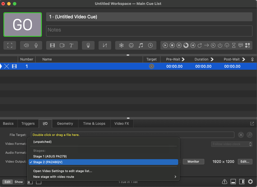
For more advanced use, though, the automatically generated stages and routes aren’t necessarily helpful because they don’t necessarily represent the actual display devices you’ll be using in performance. To understand how to prepare a workspace, therefore, you need to understand the video output pipeline of QLab.
A Video cue plays on a stage; a stage is divided into one or more regions; each region is assigned to a route; and each route connects to a device, such as a projector, monitor, or LED wall processor.
Crucially, routes can be freely assigned to devices and reassigned as needed. Routes have a specific resolution, and they can be scaled to fit any display device that is connected to the computer, and any Syphon or NDI virtual display for viewing purposes.
Setting Up A New Workspace
Before event creating a workspace, you need to make a decision about the highest resolution that your show will use. For instance, imagine you’re designing a tour which will open in a large venue equipped with 4K projectors, then travel to some smaller venues with FHD projectors. Will you build your show at 4K resolution and downscale at the smaller venues? Perhaps the bulk of the video content of your show was created at 1920 × 1080, and so you will build the show at FHD resolution and upscale to 4K for the first venue. This is a design decision, not a QLab decision, and the right answer will depend on a variety of factors.
Whatever the decision is, the first thing you should do inside QLab is create routes at the decided-upon base resolution for your show.
We’re going to walk through the setup process for a hypothetical show which will use a single 1920 × 1080 projector. Imagine you are preparing at home using a MacBook Pro with one external monitor with a resolution of 1920 × 1200.
First, set up routes
At home, with the external monitor attached, create a new workspace.
Go to Workspace Settings → Video → Video Outputs. There will be two automatically generated stages; one for the internal display of the MacBook Pro and one for the external monitor. Delete them both; the one for the internal display won’t be used, and the one for the external monitor is pre-configured to match that monitor’s resolution of 1920 × 1200, and not the 1920 × 1080 of the projector at the theater.
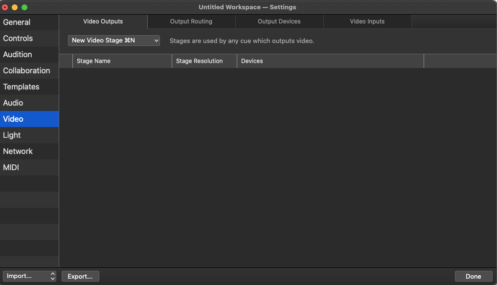
In the Output Routing tab you’ll find two automatically generated routes; one for the internal display of the MacBook Pro and one for the external monitor. Delete the one for the MacBook Pro, but leave the other one in place. Rename it “Projector”.
Click the Edit button on the right side of the window, then set the route dimensions to 1920 × 1080: the resolution of the projector at the theater.
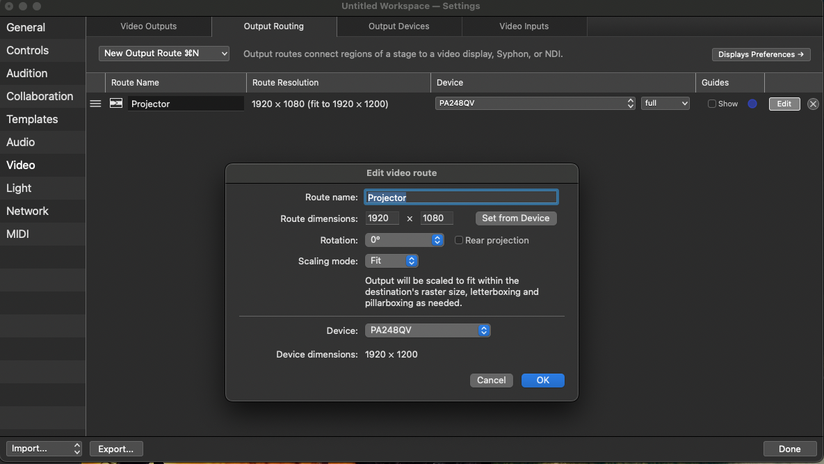
The Scaling mode should be set to Fit so that route’s entire image will be visible regardless of the resolution and aspect ratio of whatever device the output route is connected to.
The output route is now optimized for the projector that will be used for performances, but will be usable with any display connected to the computer. Currently, the secondary monitor has a resolution of 1920 × 1200, and the route will letterbox the FHD resolution to fit that monitor. Later, you might want to develop the workspace in a much more limited space, for example on a train, and use an iPad in Sidecar mode to view QLab’s output.
After connecting the iPad as an extended display in System Settings or Preferences → Displays,
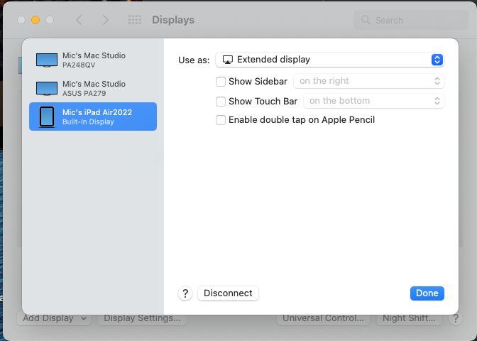
the route can be switched to use the iPad instead of the 1920 × 1200 monitor you were using at home:

Looking in the Route resolution column, you can see that the route now fits its 1920 × 1080 raster to the 2360 × 1640 raster of the iPad. Other iPad models may have different resolutions, of course.
Sometimes you may wish to work on the show when no secondary monitor is available. Or perhaps you’d like to make a screen recording of the video output alongside the QLab workspace for training or documentation purposes. You can do this by creating an NDI or Syphon output device, and assigning the route to use that virtual device instead of a physical one.
To do this, visit the Output Devices tab and click the New Virtual Device button.
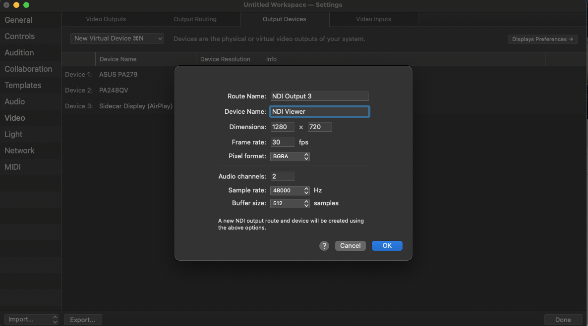
The name, resolution, and frame rate of the virtual device are all up to you, but keeping the resolution and frame rate low can keep processor use under control.
Creating a new virtual device also makes a route for it, which is not helpful in this case because you already have the route you plan to use. To keep things uncluttered, we recommend returning to the Output Routing tab and deleting the new route.
Set the “Projector” route to use the new virtual device. As before, the route will scale to fit the device’s resolution.

When it’s time to bring the show to the theater, simply connect the theater’s projector to your computer and set the “Projector” route to use it for output.
Next, set up stages
Now that this route is configured properly, you can create the stage or stages that you plan to use in your design.
The simplest setup is a single stage with a single region that sends the full raster of the stage to the full raster of the route.
Go to the Video Outputs tab and create a new empty stage by clicking the New Video Stage button and choosing Empty Stage from the pop-up menu. The stage editor window will open to allow you to configure the stage you just created.
Create a new region in the new stage by clicking New region with output… and choosing “Projector”, which is the route you configured in the last step. Whatever text is in the parentheses next to “Projector” can be ignored; it’s just showing the device that the route is currently set to use.
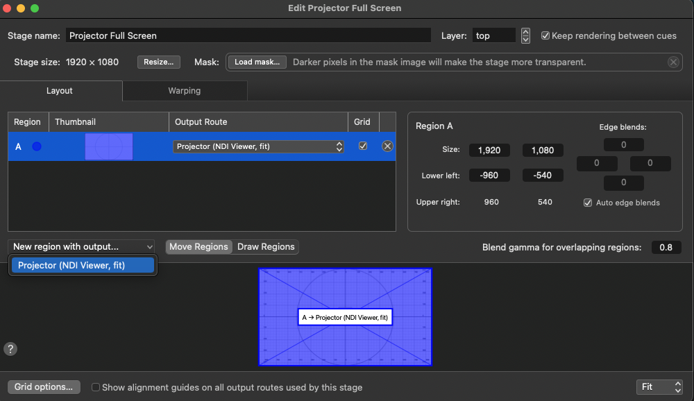
Tick the Grid checkbox to display the stage’s grid on whatever video device the route is currently using. If you change the device that the route is using, you may need to toggle the grid on and off to see it displayed on the new device.
Here’s the grid displayed on a software NDI monitor app. In this screen shot, the route is assigned to use the NDI virtual device we talked about earlier.

Stages and Regions Refresher
In QLab 5, a Video cue sends pixels to a stage. The stage is divided into one or more regions which send pixels from the stage to an output route. Each region can be placed anywhere within that route and warped to a different shape. This process is commonly referred to as mapping, and it allows video to fit irregular projection surfaces precisely.
Here’s an example:
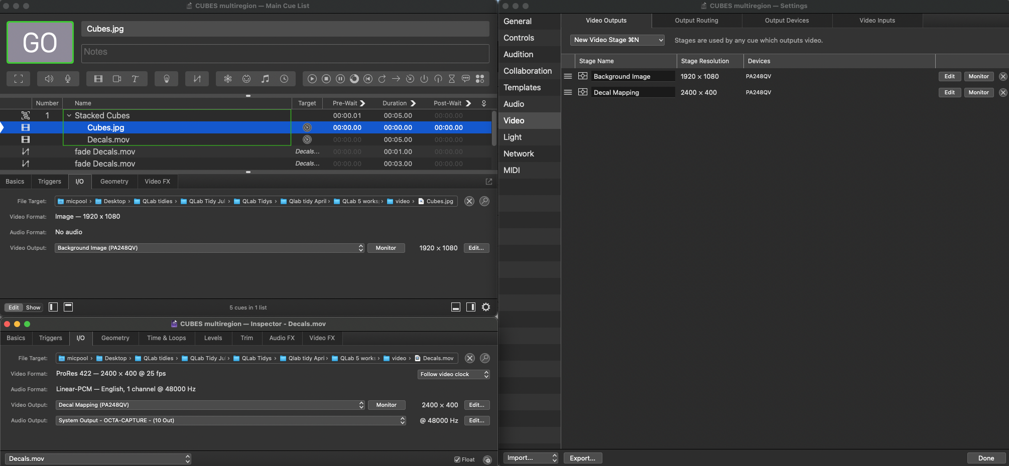
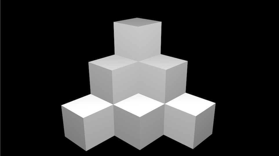
Using a Video cue, a picture of a stack of cubes is sent to a stage named “Background Image”. That stage is routed to the full-screen display of a secondary monitor. This represents a physical stack of cubes that we are planning to use as our projection surface. We would like to project video onto all the visible faces of every cube, with each face mapped individually as an individual stage.
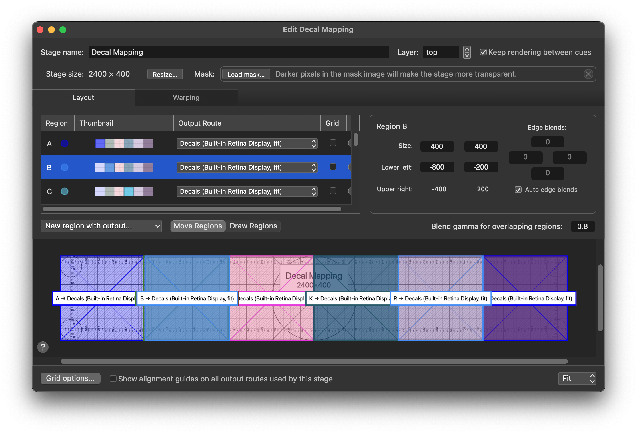
Another Video cue plays a movie consisting of six square animations, arranged side by side. This cue is assigned to use a different stage named “Decal Mapping”. This stage has dimensions which match the movie, 2400 × 400.

On the “Decal Mapping” stage, each of the six square animations can be mapped as the area of interest by creating a region which fits one of the animations. In our background image, there are six cubes with three visible faces each, so we need 18 regions to cover those 18 faces.
In the example, the three rotating star animations are mapped to the top surfaces of each cube, and the checkerboard animations are mapped to the front faces. This is possible because more than one region can cover the same portion of a stage. The stage has 18 regions, which are automatically given letter names A through R.
Here is region B selected in the Layout tab of the stage editor window. The region is set to a size of 400 × 400 and it covers the part of the stage where the red star appears in the animation.
In the Warping tab, region B is mapped to fit the top surface of the lower left cube.
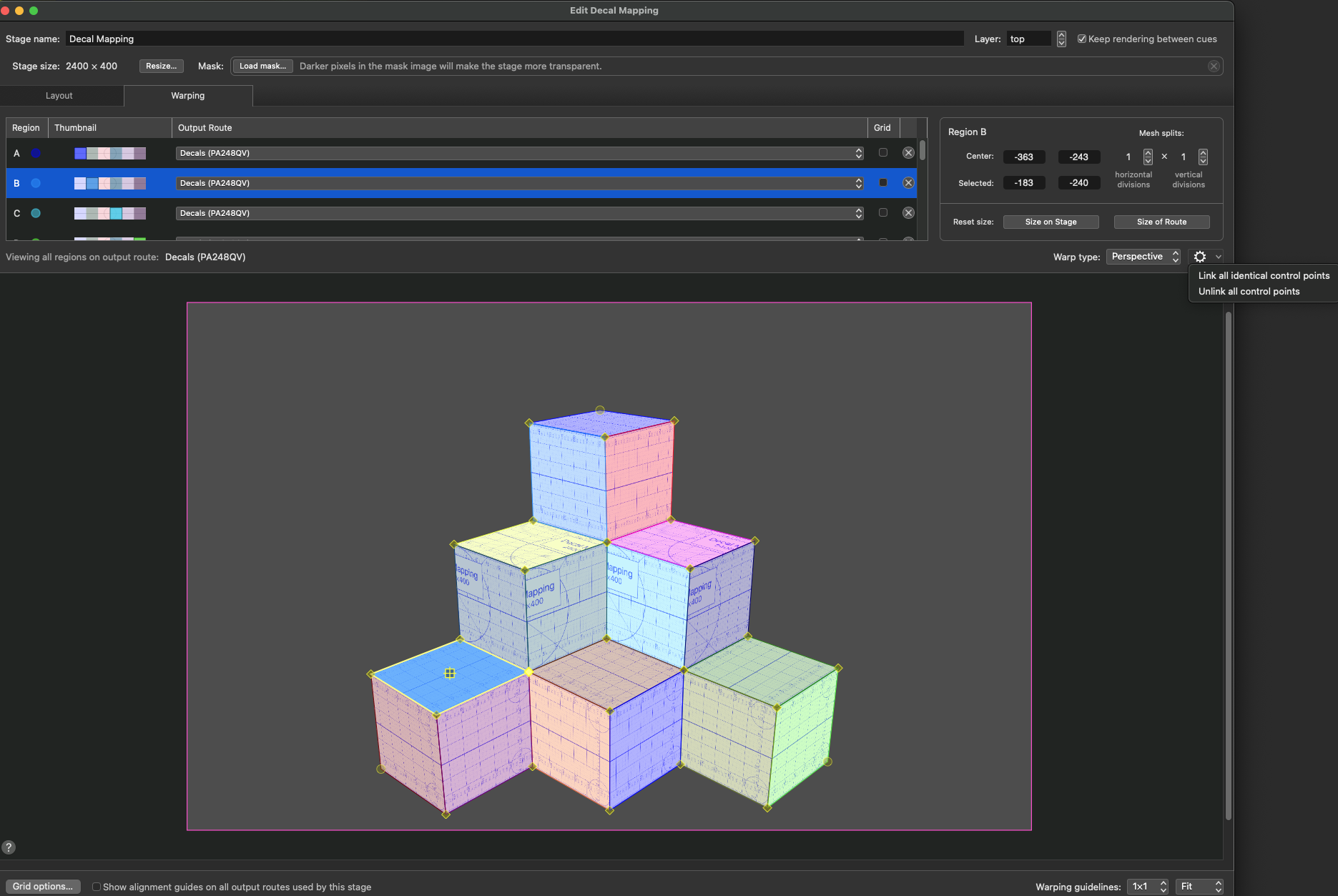
All the Regions are set up in the Layout pane to enclose one of the six animations in the video, and each Region is warped to fit one of the 18 visible surfaces of the stack of cubes.
In addition, all the identical warping control points of the regions have been linked using the cog pop-up menu on the right of the pane. This means all the control points af all the regions can be adjusted as a single mesh, which considerably speeds up the process of fitting the mesh to the projection surface.
When Video cues are played to the “Background Image” stage and the “Decal Mapping” stage simultaneously, each stage outputs its warped regions to their respective routes, and from there to the route’ selected video device. The combined result looks like this:
Projection mapping is examined further in several other cookbook chapters. The “cube stack” demo shown above is also available to download from this chapter.
Unless you happen to have the exact same monitor that was used to build the demo, you will need to modify the video settings of the downloaded examples to use a display connected to your computer. As we saw earlier, all you need to do is open Workspace Settings → Video → Output Routing and assign both routes to use the display device attached to your Mac.
In this screen shot, the “cube stack” demo has been downloaded onto a different MacBook Pro without an external monitor attached.

In Workspace Settings → Video → Output Routing, two routes are set to use the MacBook Pro’s built-in retina display, fitting the 1920 × 1200 routes of the workspace to the 3024 × 1964 resolution of the display.
A Remarkable Property of QLab Stages
By the time a video gets to a stage, all the heavy lifting of reading the video file from storage, decoding it, applying video effects, etc., has been done. A video on a stage can be used by a few regions, as in the previous example or by literally hundreds of regions (on a fast Apple Silicon computer) with minimal impact on the processing power required.
In the screen recording below, a small square animation is used in 45 regions without any significant load being placed on the graphics processing capabilities of the computer. Then, in a more demanding test, the animation is replaced with a few 4K videos; 45 instances of 3 videos. The computer handles this with relative ease.
Pre-Visualization to Performance
QLab’s ability to effortlessly play multiple copies of precisely mapped images can be exploited to develop a workspace that will simulate the actual arrangement of displays, allowing you to approximate a design before access is available to the performance space or the projectors.
Once it is possible to start working in the actual space, the output of the placeholder projectors can be changed to the real projectors, optionally keeping the pre-visualization display so that work on the design can be continued after hours or off site.
Once the design is complete, the pre-visualization regions can be disabled to maximize the performance of the workspace or to free up the video output the pre-visualization was using, but in many cases it will be possible to retain it as a confidence monitor for an operator who perhaps doesn’t have a full view of all the projection surfaces. Because the pre-visualizations are derived from the same stages as the show outputs, an operator can be confident that an image appearing in the pre-visualization is precisely what is being shown on the projector, barring physical problems with cabling and projectors.
The downloadable example shows a representation of two views of the future performance space, together with a straight-on, close-up view of each of the five projection screens.
The installation uses five projectors:
- Projectors 1 and 2 are blended to cover a very wide screen behind the side seating block.
- Projectors 3 and 4 do the same thing for a screen behind the opposite seating block.
- Projector 5 covers three overlapping round scenic elements.
The workspace contains six stages:
- one for each of the wide screens.
- one that covers all three discs as a single stage.
- one for each of the individual discs.
QLab’s workspace will be visible on the Mac’s primary monitor, and a secondary monitor will be used to view the pre-visualization.
Using the Tutorial
There are three main ways to use this tutorial.
To cover the topics in the greatest detail, you can use this chapter to re-create the workspace from scratch. This will help you develop an understanding of every step of the process and is recommended for those who have little or no knowledge of QLab’s advanced video features and want to learn the.
For those who already have a solid understanding of video in QLab 5, you can download the workspace and read the tutorial as a guide to how it functions.
Finally, the downloaded workspace can be used as a pre-made playground to experiment with video content. The included short demonstration can be run and reprogrammed to do different things, using other images and video files.
Here’s what the demo looks like in action. Best viewed full-screen.
Warning: contains strobing images.
Setting Up The Workspace
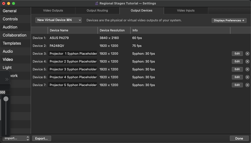
In Workspace Settings → Video → Output Devices, any displays already attached to your computer will automatically be listed.
We’re going to create Syphon outputs which will act as placeholders for each of our projectors. These should be created at the maximum resolution of any projector you anticipate using with this workspace; in the example we’ll use 1920 × 1200. Remember that creating a virtual device automatically creates an associated route. Name these routes with the number of the projector that will eventually be used with that route plus, optionally, a description of that projector’s function:
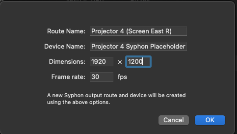
Repeat for each of the five projectors. Here’s the completed Output Device tab:
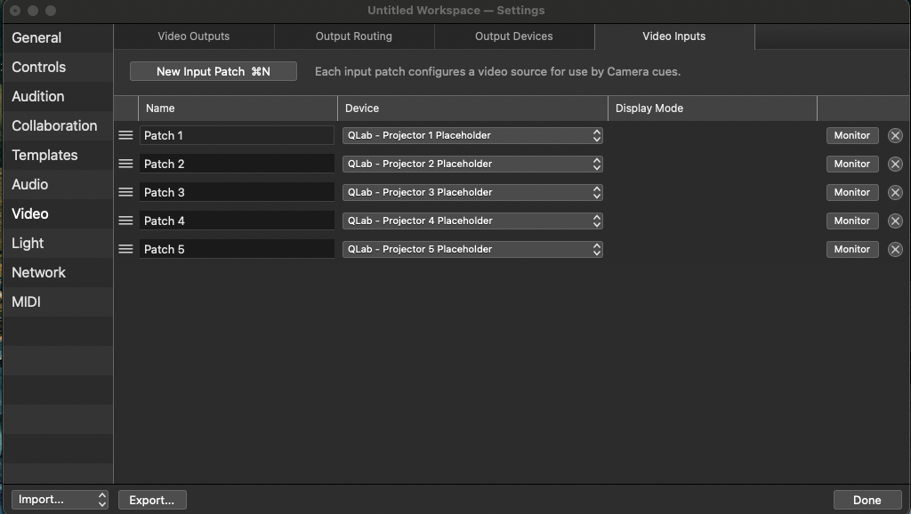
Next, in Workspace Settings → Video → Video Inputs, we’ll create one video input patch for each of the five Syphon devices. This will allow us to create Camera cues which display the output of each “projector”. We’ll use these Camera cues to preview that output.
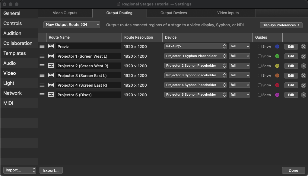
Now go to the Output Routing tab. You’ll see one route for each output device, including the five Syphon virtual devices you created earlier.
Delete the route corresponding to your main display, where you’re viewing your workspace. This will make it impossible to accidentally display cues on that display, obscuring QLab.
If you have a secondary monitor connected, make sure it has a route. Name that route “Previz” and delete the Syphon Previz route. If you don’t have a secondary monitor attached, then rename the Syphon Previz route to “Previz”.
Any time you want to change the display where “Previz” appears, you can simply change the device for the “Previz” route in this tab. If you were working on a train, you could switch “Previz” from your disconnected secondary display to a Syphon output or a iPad connected via Sidecar.
The completed Output Routing pane should look like this:
Next, we set up stages.
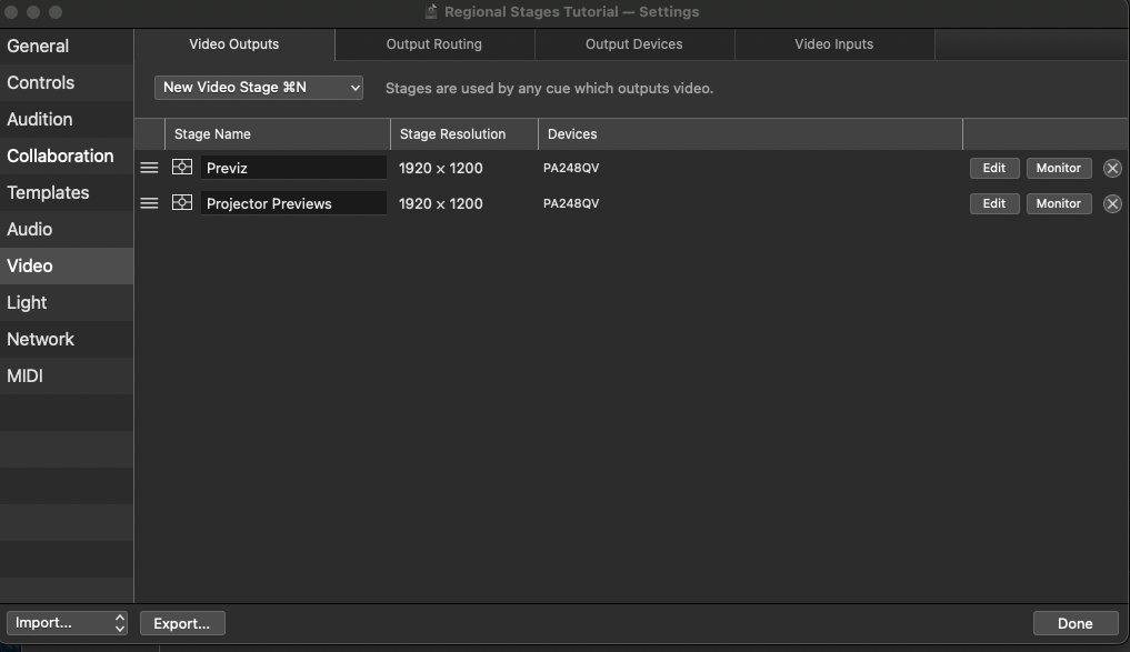
In a new workspace, the Workspace Settings → Video → Stages tab will contain default stages for any currently connected monitors.
Delete the stage for the display you are using to view QLab.
Name the stage associated with your secondary monitor “Previz”.
Duplicate this stage by copying and pasting it, and name this new copy “Projector Previews”. We’ll use this stage to display the video signal that will be sent to each projector, using the video inputs we set up previously.
The next step is to create the simulation of the performance space. This requires images of the projection surfaces as seen from audience viewpoints in the space. These could be photographs of the performance space with screens added in Photoshop, photographs of a physical scale model of the set design, photos of the set itself as it is being constructed, or renderings from a draftsperson or CAD program.
In our example, we are going to use 3D renderings of two audience views and a straight-on close-up view of each of the projection surfaces.
Close Workspace Settings and drag these images into the your cue list. Put them in a Timeline Group cue named “Previz”, select them all, and navigate to the IO tab of the inspector. There, set their video output to the Previz stage. In the Geometry tab, set their mode to “Custom”.
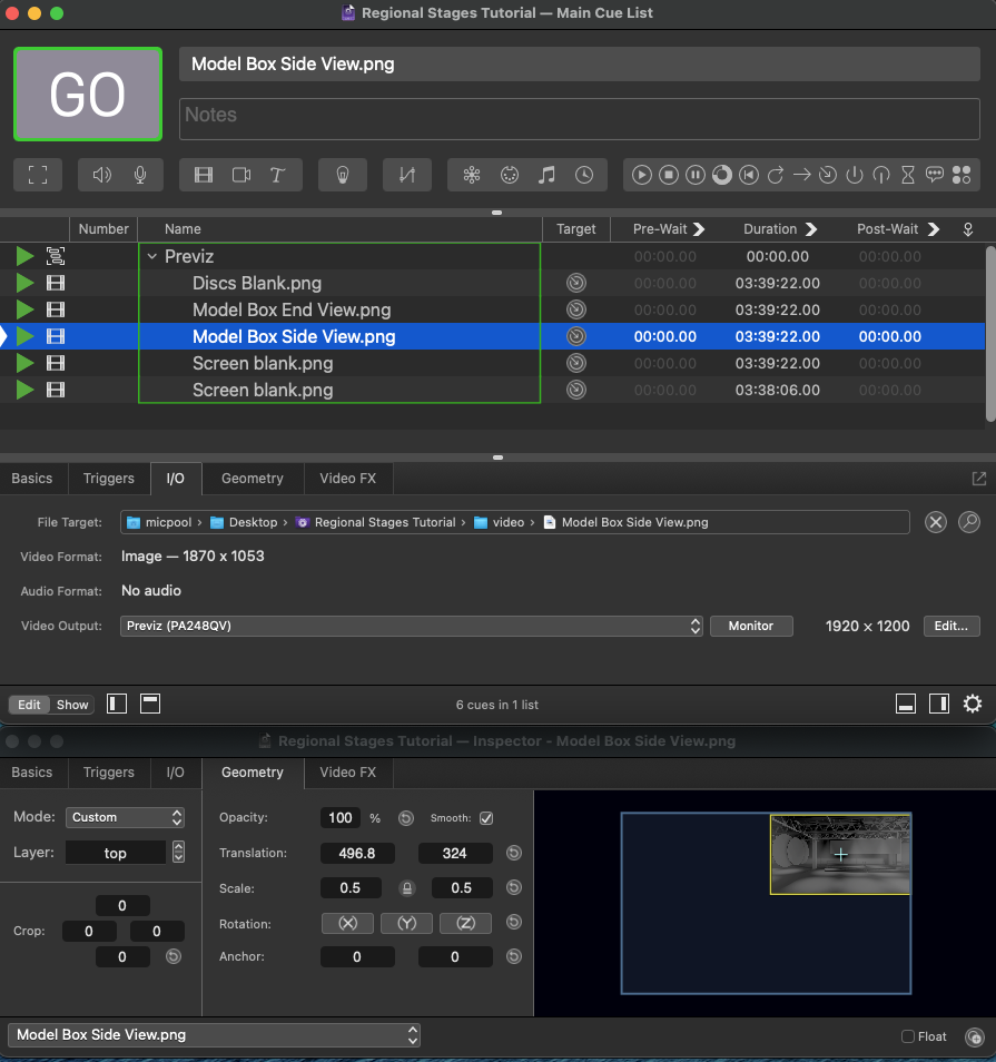
Start the Group cue and set the translation and scale of each Video cue to arrange the images on the previz display so that all the images can be clearly seen.
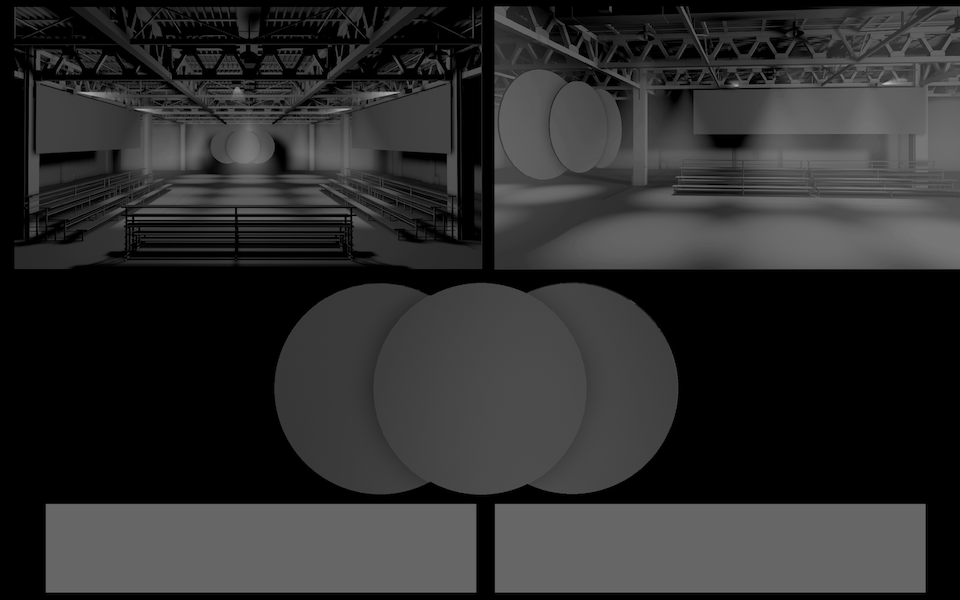
Now that the previz display is ready, you can create a stage for each projection surface.
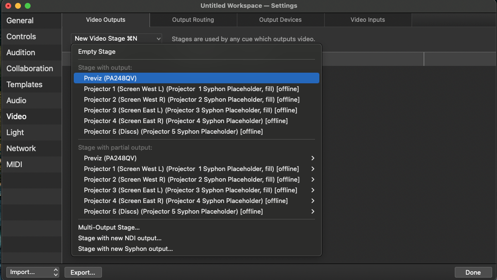
In the example, the first two projection surfaces are covered by two overlapping projectors each, i.e. they are multi-output stages. These are easiest to set up using the built-in tool to calculate the overlap and pixel dimensions of the full screen.
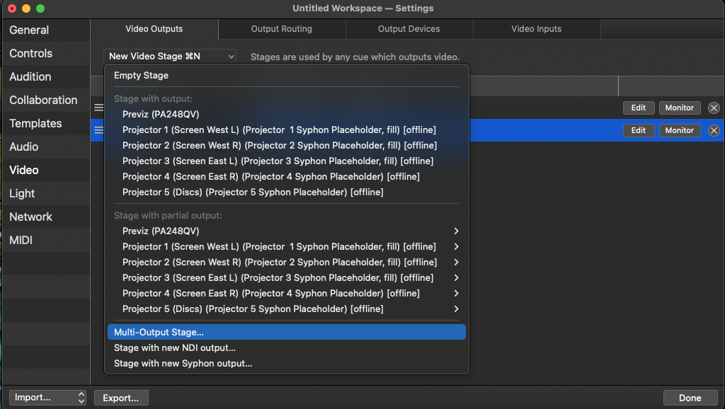
Click New Video Stage and choose Multi-Output Stage… from the pop-up menu.
The example uses two 1920 x 1200 projectors side by side, overlapping by 20%, so we enter that resolution, arrangement, and the required overlap into the text fields.
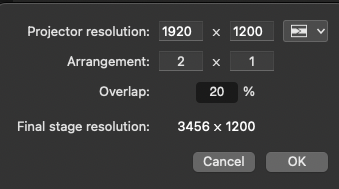
QLab automatically calculates the width of the complete projection surface: 3456 pixels. Ideally, any content that will be projected onto these stages should be created using that width.
Click OK to create the stage and open the stage editor.
Change the name to the projection surface name, e.g. “Screen West”, and assign the two routes which represent the relevant projectors to the two regions of the stage by selecting them from the Output Route pop-up menu in the Layout tab.
Edge Blends are automatically calculated for the overlapped regions.
If we were projecting at the native aspect ratio of the multi-output stage, i.e. 3456 (width) divided by 1200 (height), or a ratio of 2.88:1, that would be all that was required. In our example, though, the projection surface that the scenic designer has given us is much wider than that. In the drawing, it measures 20 meters by 4 meters, or a ratio of 5:1. We know the width of the screen will be covered by the full pixel width of the stage, but we need to do some calculations to derive the height. The equation is:
( pixel width / screen width ) * screen height
For us, that’s ( 3456 / 20 ) * 4 = 691.2, which we can round to 690 for convenience. Full-screen content for this stage should optimally be created with pixel dimensions of 3456 × 690, and this stage can be resized to those dimensions using the Resize button (unticking the preserve aspect ratio checkbox.)
When you resize a stage, the regions get resized as well so we need to restore these to their original widths of 1920. To do this, select Region A by clicking on it in the layout tab and drag its edges to fill the entire grid. Then restore its width by entering 1920 × 690 into the size fields on the right. Repeat this process for Region B, then drag it to the right side of the stage.
The Layout tab should now look like this:
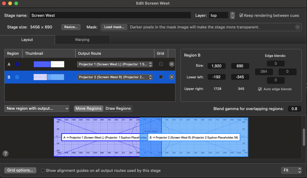
We now need to set the position of the two regions with their respective output routes in the warping tab.
Go to the Warping tab, select Region A, and click on the ‘Size on Stage’ button. Repeat for Region B.
The Warping tab should now look like this:
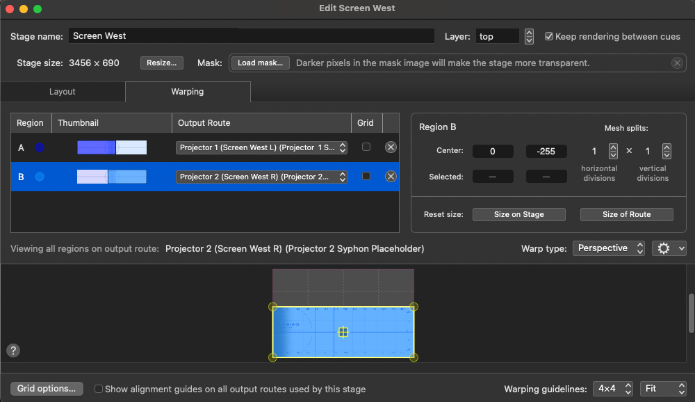
Close the editor, duplicate the “Screen West” stage using copy and paste, and rename the stage “Screen East”.
Click the edit button for this new stage and change the routes to Projectors 3 and 4
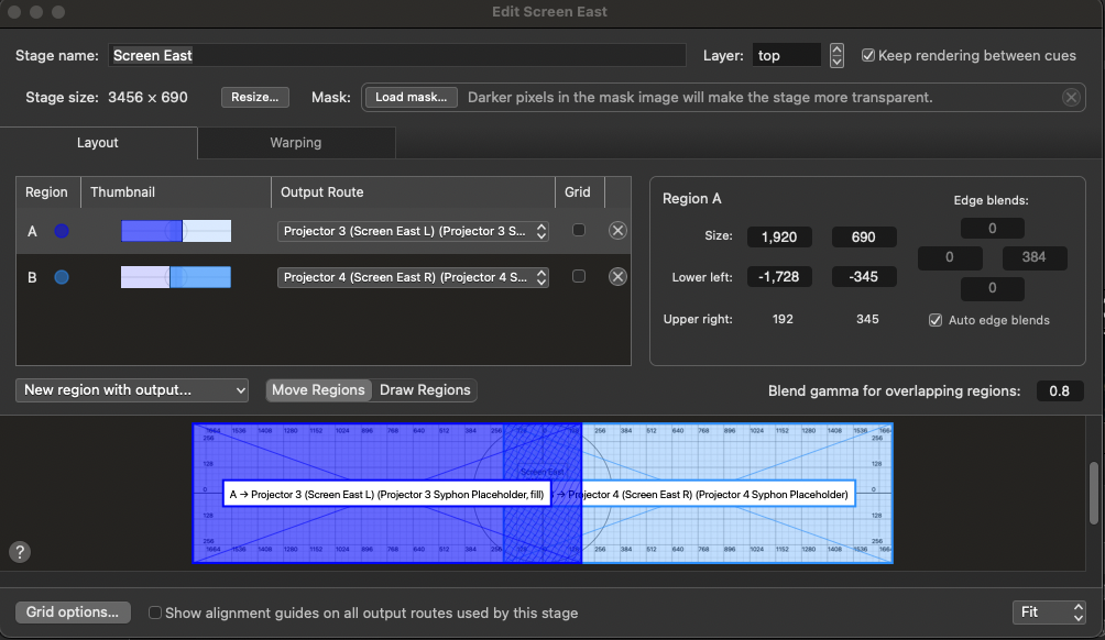
That was considerably quicker!
The fifth projector in the example is used as the output for four stages. One stage projects onto all three discs, treating them as a single entity, and three more stages each cover one of the discs.
Since stages in QLab are always rectangles, masks are required to make the stages perfectly fit the circular scenic pieces.
Making and using masks
In Affinity Photo, Adobe Photoshop, or a similar image editor, make a new document with pixel dimensions that match your projector (1920 × 1200 in our example.) Paste in a drawing or photograph of your projection surface, lock its aspect ratio, and scale it to fit just within the screen.
Select the circles, and on a new layer, fill them with white on a black background and blur the image by 1 or 2 pixels. Export as a JPG and name the file “All discs Mask 1920x1200”.

Select just the middle circle and, on a new layer, fill that selection with white on a black background. Crop the image to a square, leaving a small black border around the circle and resize that to the nearest even-numbered value, e.g. 1000 × 1000. Export as a JPG and name the file: “Circle Mask 1000x1000”.
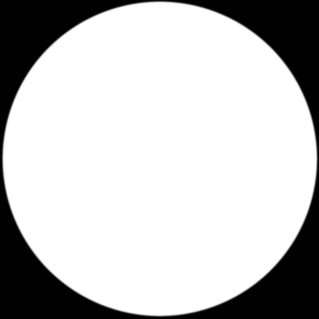
Back in QLab, in Workspace Settings → Video Outputs, click New Video Stage and make a new stage with output Projector 5. Name this stage “All Discs”, and drop the “All Discs Mask 1920x1200” image into the mask well.
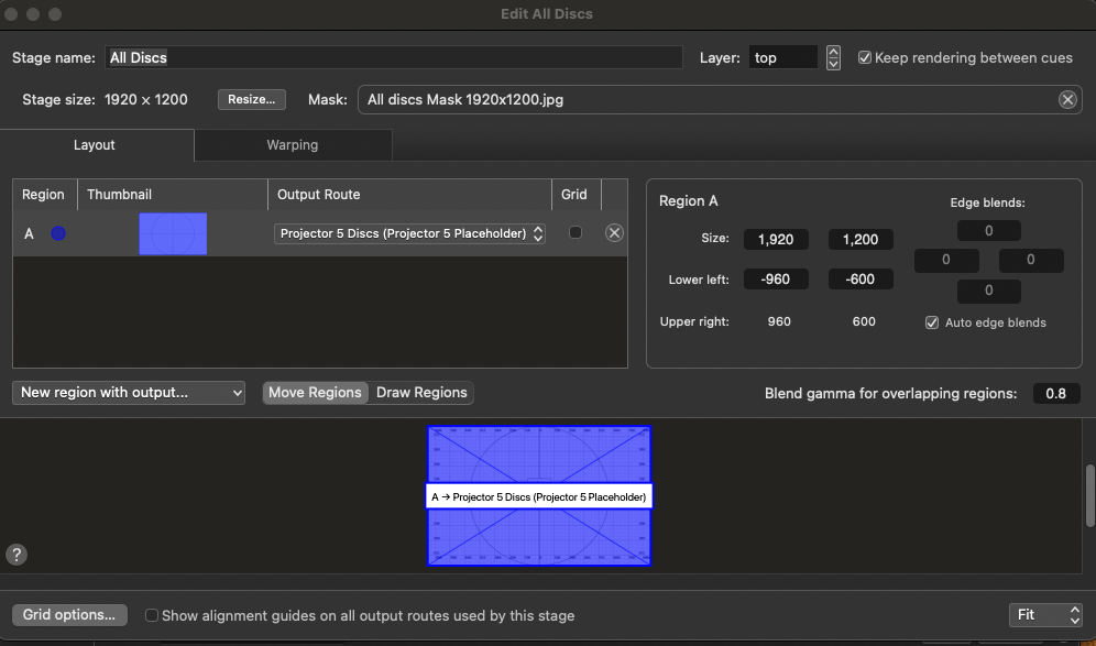
Close the stage editor and make another new stage with output Projector 5. Name this one “Disc L” and resize it to the square mask dimensions, e.g. 1000 × 1000. After resizing the stage, resize the region to cover the whole stage.
Drag the “Circle Mask 1000x1000” image into the mask well.
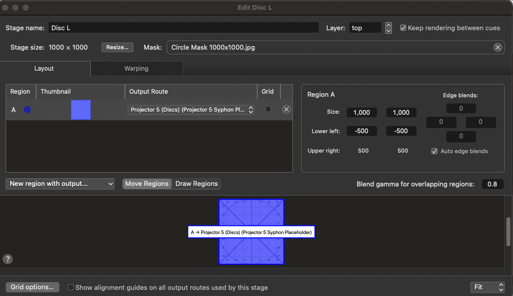
Close the stage editor, then duplicate this stage twice by copying and pasting. Name the two duplicated stages “Disc R” and “Disc C”.
Setting layers
We now need to set the layer order of the stages, so that the right images appear on top of each other, and make a grid for each stage which we’ll use to align our stages in the previz view.
Open the stage editor window for each stage, one at a time, and set the stages’ layers as follows:
| Stage | Stage Layer |
|---|---|
| Previz: | Layer 1 |
| Projector Previews: | Layer 31 |
| Screen West: | Layer 11 |
| Screen East: | Layer 11 |
| All Discs: | Layer 12 |
| Disc L: | Layer 13 |
| Disc R: | Layer 13 |
| Disc C: | Layer 14 |
While the stage editor window is open for each stage, click the Grid options… button in the lower right corner and then click Export Grid Image…
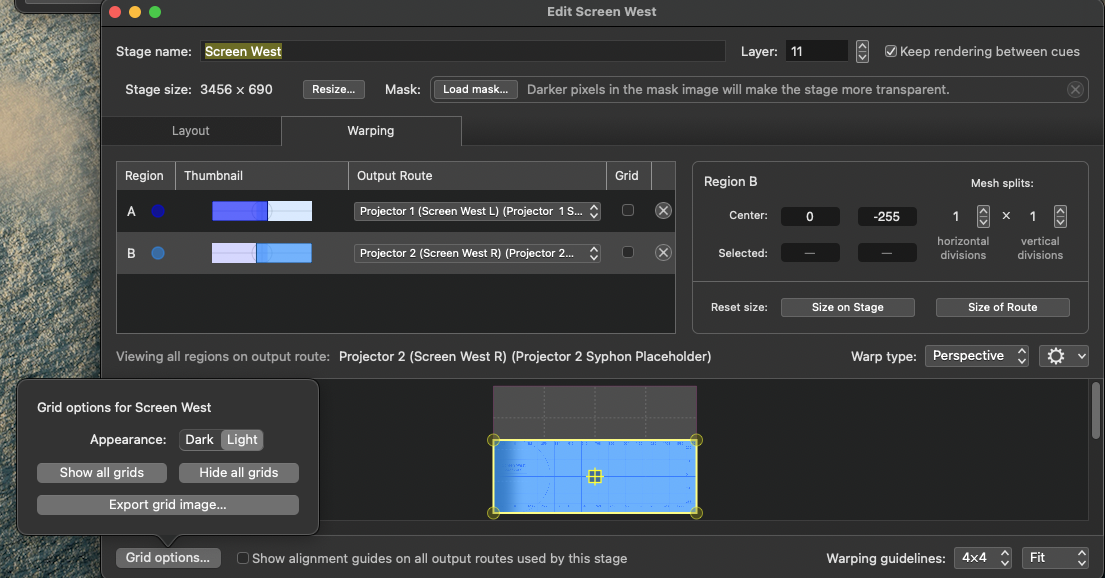
Now return to the cue list and make a Timeline Group cue containing one Video cue for each of the exported grids. In the I/O tab of each Video cue, set the video output of the cue to the appropriate stage, e.g “All Discs” to “All Discs (Projector 5 Placeholder)“.
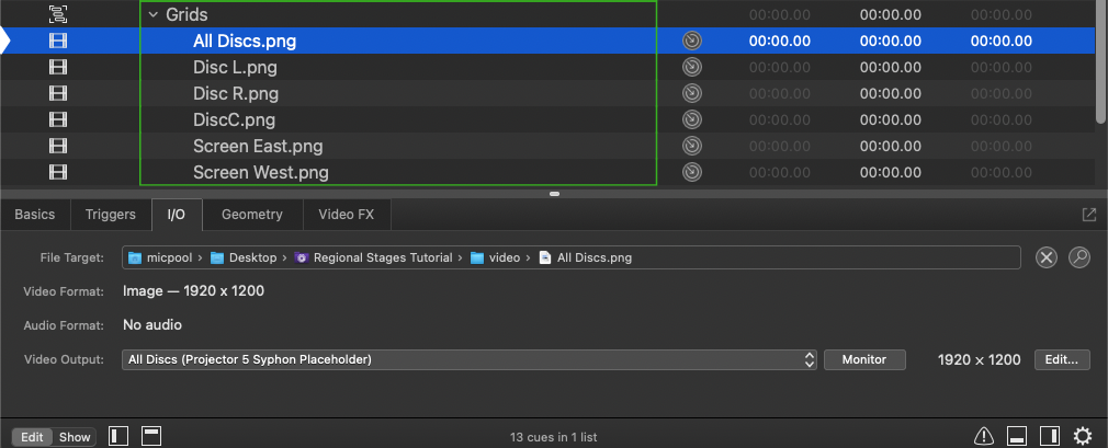
Projector Previews
Next, we want to be able to view the projector placeholders in order to make sure that each projector is receiving the correct imagery. To do this, create another Timeline Group cue after the “Previz” Timeline Group and name it “Projector Previews”. Inside this new Group cue, create a Video cue with a solid dark blue image set to full stage. Alternately, you can use a Text cue with a 10000 point blue square emoji. The downloadable example uses a Text cue. Create another Text cue with the text “Projector Previews (Syphon Placeholders)“. This cue will make it clear when the “Projector Previews” Group is active.
Next, create five Camera cues. In the IO tab of the inspector, set each Camera cue’s video input to one of the five video input patches we set up earlier. Name each Camera cue with its projector number.
Next, we want to configure the workspace to allow us to toggle between the “Projector Previews” Group and the “Previz” Group. Select both Group cues and navigate to the Triggers tab. On the right side, check the box labeled When starting the action of this cue set the accompanying pop-up menu to fade and stop peers. Set the over time value to 0.
Next, assign Hotkey Triggers to the two Groups. The example uses 1 for Previz and 2 for Projector Previews. A useful convention for any cue that has a hotkey trigger is to number it with the hotkey inside a square bracket.
Select both Groups again, and create a new Group cue. This will place both preexisting Group cues inside the new Group cue. Set the mode of this Group cue to “Start First”, and its name to “TOGGLE VIEW”.
By placing the two Group cues within an enclosing Group cue, they become peers, and “fade and stop peers” means whenever either of them starts, the other will be stopped. In a show workspace, these two groups would probably be tucked away in another cue list, so the enclosing group would not be necessary. To make everything clearly visible for the demo, we are using an enclosing group to make them peers in the main cue list so they toggle independently of other cues in the list.
The cue list should now look like this:
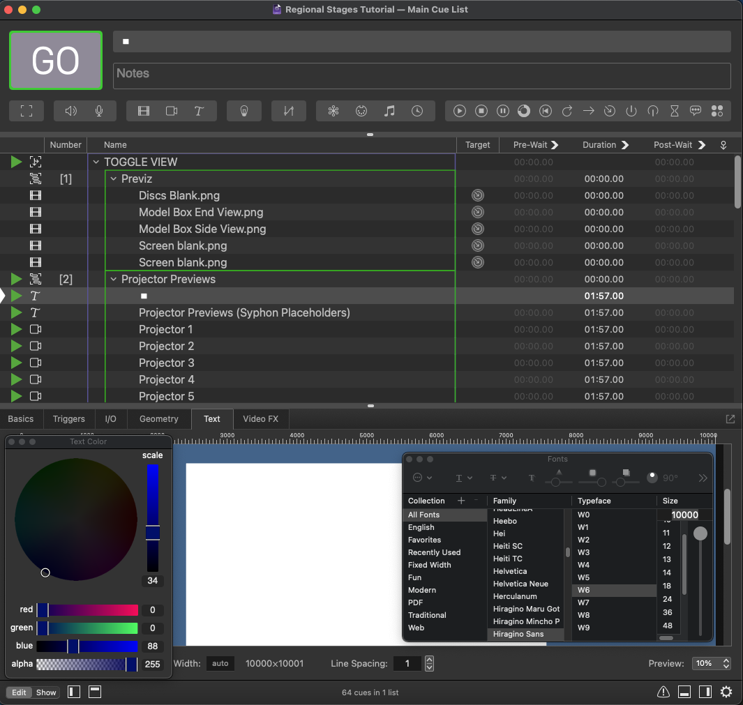
Now that the cues are operating correctly, we’ll arrange the projector preview cues on screen.
Start the “Grids” Group cue and the “Projector Previews” Group cue.
Select all the Camera cues in the “Projector Previews” Group and navigate to the Geometry tab in the inspector Set their Mode to Custom and their scale to 0.4.
Set the translation of each Camera cue so that the output of each projector can be seen clearly. In the example, the left and right halves of the two edge-blended stages have been separated to view them independently, but you can overlap them in order to view them as whole, blended stages if you prefer.
Here, we can see projectors 1 and 2 have their edge blends correctly set and that projector 5 is displaying all the disc stages but that the individual disc stages are not aligned.
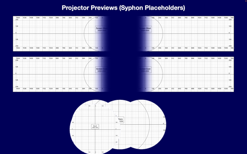
To align the individual disc stages on projector 5, open the stage editor for one of the single-disc stages and go to the Warping tab. There, move the region and watch the grid cues on the secondary monitor. Keep moving the region until the grid image on the single-disc stage aligns with the grid image on the “All Discs” stage.
Repeat this process for the other two single-disc stages.
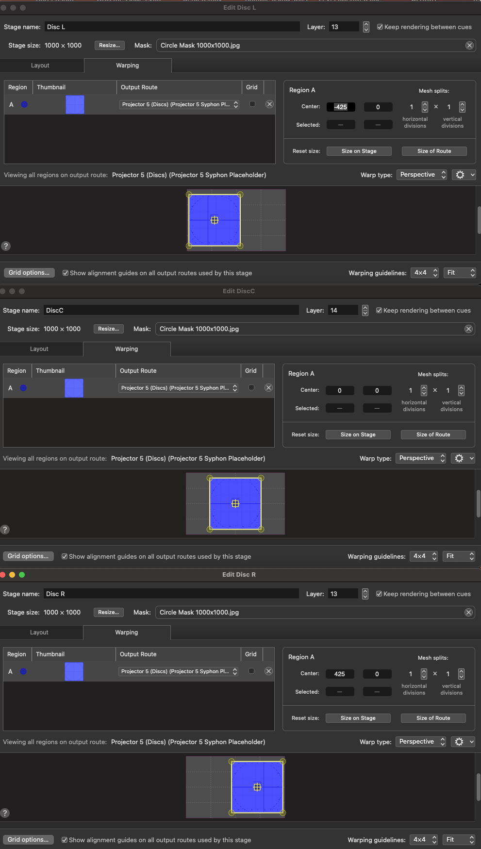
The discs are now in alignment and, by virtue of the stage layers, the single-disc stages are visible on top of the “All Discs” stage, and the middle disc is on top of the two sides.
All the stages are now displayed on the projector placeholders. When the actual projectors are connected, the output routes can be switched from using the Syphon virtual projectors to the actual projectors, and everything will work immediately.
The Previz screen
Leave the grids playing, but toggle to the Previz screen by starting the Previz group cue.
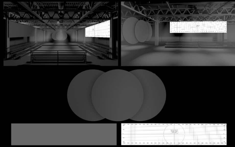
To begin with, none of the stages are visible on the screens in the 3D drawing of our performance space. To make them visible, we need to create regions on each stage which will send video to the appropriate area in the drawing.
Let’s start with “Screen East”.
This screen appears three times in the Previz:
- a close-up view in the lower right corner;
- in the left audience perspective image, on the audience-right side;
- in the right audience perspective image.
Open the Screen East stage in the stage editor and create three new regions using the “Previz” route.
Select each new region and drag the edges of the region so that it covers the entire stage.
Switch to the Warping tab. Here, drag the control points of all the new regions to make them much smaller. The size and shape isn’t important right now; you just want to make sure the grid images don’t obscure the previz background image.
To speed this process up a little, you can start by using the cig menu to link the control points, then shrink the regions down, then unlink the control points.
Select region C and resize it to fit the close-up view in the lower right corner of the previz background image. It’s usually easiest to roughly place each control point with the mouse, the use the arrow keys for fine-tuning.
Select region D and align it to the audience-right projection surface in the left audience perspective.
Select region E and align it to the rectangular projection surface in the right audience perspective.
The stage editor and previz on the secondary monitor should now look like this.
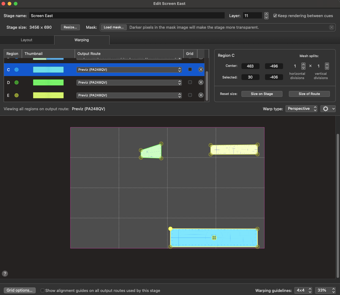
Repeat this process for the “Screen West” stage. Since that stage is only visible twice in the previz image, you’ll only need to create and move two new regions.
Repeat the process again for each of the disc stages, which are visible three times in the previz image.
Warping the discs onto the right audience views is a bit tricky because the angle is so dramatic; the best way is just to keep going around each control point in turn until it fits. Each time you go around, the adjustment required gets much smaller!
It will also be easier if you set the control points to create a very small image initially and move the points out. It can also be easier to turn off all the grids besides the one you’re working on when dealing with overlapping surfaces.
When you have finished, stop all cues (press escape) and start the “Grid” Timeline Group again. You should see all your grids over a black background.
Now start the previz background image by using its hotkey. Because of stage layers, the previz image will appear behind all the grids.
You now have a completed Previz with every stage properly aligned to each projection screen.
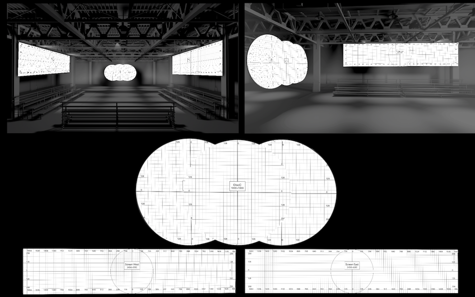
All this might take a few hours or even a day for a complex design. Once it’s completed, though, you will have an environment in which the projection design can be created in an accurate representation of the performance space. Importantly, the design will be show-ready (or nearly so) before you arrive at the venue for load-in, focus, and technical rehearsals. This will allow for much better decision-making regarding content and programming, allow other team members to see your work as it develops, and facilitate discussion of your design in the context of the space in which it will be performed.
When the design is installed, all that is required is for the actual projectors to be substituted for the virtual projectors, a minute’s work at most!
Switch the grids off and enjoy creating with some real footage.
There are a few images and videos in the video folder of the downloadable demo to get you started.
The example workspace contains a duplicate of the “All Discs” stage, named “All Discs Overlay”, on stage layer 21. This is used in the demo video for text overlays over all the individual disc Stages.
All images AI-generated using Photoshop’s generative fill or Stable Diffusion.
Drive-by video © Mic Pool, all rights reserved.