Video Output
The video output system of QLab 5 supports a wide variety of workflows and setups, from a single TV built into a set, to multi-projector blends mapped onto complex scenery, to LED walls, to broadcast feeds. This section of the manual will take you through all the steps necessary to fully configure video output, but it will also help guide you to simple solutions when that’s what you need.
All aspects of video output are configured in Workspace Settings → Video.
Video Terminology
QLab uses the following terminology in the realm of video. Care has been taken to make sure these terms are approachable and not ambiguous, but nevertheless it can be difficult to keep track of. Here is a brief glossary of the essential video terms in QLab.
- A stage is a sort of virtual raster1 to which Video, Camera, and Text cues are assigned. The imagery created by those cues is displayed on the stage, and the stage is displayed on screens, projectors, NDI streams, and Syphon outputs.
- A region is a section of a stage which will be displayed on a device. A region can cover the whole stage or just a part of it, and multiple regions can overlap or not as needed.
- An output route or simply route is the intermediary between regions and devices. Regions are assigned to routes, and the route takes care of the particulars of sending video to the assigned device. This intermediary makes it possible for cues, stages, and regions to behave consistently even if you need to trade out your devices for other hardware.
- A device is QLab’s internal representation of an actual, physical video display device such as a computer monitor, television, video projector, or LED wall. A device can also be an NDI output or a Syphon output, since these have the same function as a physical video display.
Using Video Without A Video License
QLab can be used for video without a license installed, which allows you to address simple video needs without spending any money on QLab. You can find a list of which features are free and which require a license from the Features section of this manual.
When no video license is installed, video output from QLab is restricted to a single device.
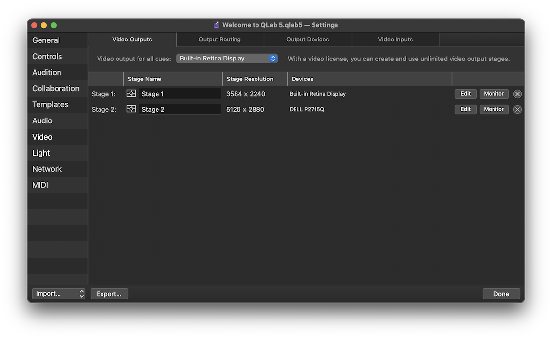
The pop-up menu at the top of the Video Outputs tab, labeled “Video output for all cues”, allows you to select a single device connected to your Mac. Any device which appears as a display in the macOS Displays preference pane will be available here. Whichever device you choose will be used by all video output from your workspace. You do not need to adjust cues if you change this setting; every cue is automatically routed to the device selected here.
The remainder of this section of this manual assumes the use of a video license. If you use QLab without a video license, you may find the rest of this section of the manual unnecessary.
Getting Started
When you create a new workspace, QLab will automatically create a stage for each display connected to your Mac. If you don’t need anything fancy, you can start programming cues as quickly as possible. If you need something more specific, you can edit these stages to suit your needs or delete them and create your own stages.
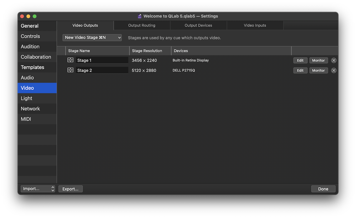
This screen shot was taken on a 2021 16” MacBook Pro with a 5120 × 2880 monitor connected to its HDMI port. When this workspace was created, QLab automatically created Stage 1 with the MacBook Pro’s internal display assigned to it, and Stage 2 with the external monitor assigned to it.
The stages in the workspace are listed in a table with several columns.
- The Stage Name column lets you see and edit the name of the stage. Note that if you plan to use OSC to control a stage by name, you must give the stage an OSC-compatible name, i.e. one without spaces or special characters reserved by the OSC spec.
- The Stage Resolution column shows the pixel dimensions of the stage. The automatically created stages in this screen shot have the same dimensions as the devices that they are assigned to use, but stages can be any size up to 16384 × 16384, limited of course by the processing power and memory available on your Mac.
- The Devices column lists the devices in use by the stage. The automatically created stages have one device each. A stage that uses multiple devices would list them here separated by commas.
- The Edit button opens the video stage editor, which allows you to change the properties of the stage. The video stage editor is discussed below.
- The Monitor button opens a monitor window for the stage.
- The button deletes the stage. This is an undo-able operation, by the way.
To create a new stage, click the New Video Stage button. When the Video Outputs tab is open and frontmost, the keyboard shortcut ⌘N (which ordinarily creates a new workspace) is a shortcut for this button. The button opens a pop-up menu to allow you to create a new stage with some initial settings if you so choose.
- Empty Stage - create a new stage with a resolution of 1920 × 1080 pixels and with no regions created, and no output routes assigned.
- Stage with output - listed under this heading are the output routes defined in the workspace. Choosing one will create a new stage with the same resolution as the route and configured to output to that route. This is essentially what QLab does to create the default stages in a new workspace.
- Stage with partial output - each output route in the workspace is listed here again, but each with its own sub-menu that allows you to create a stage that’s the same size as a portion of that output only. Partial outputs are discussed below.
- Multi-Output Stage… will prompt you to describe a multi-projector setup, including the number of projectors, their resolution, and their physical arrangement. QLab will then create a stage that is pre-configured to work with that projector layout.
- Stage with new NDI output… will prompt you to create and configure a new NDI output. QLab will then create a stage using that output. NDI outputs are discussed below.
- Stage with new Syphon output… will prompt you to create and configure a new Syphon output. QLab will then create a stage using that output. Syphon outputs are discussed below.
The Video Stage Editor
We’re not going to lie to you; the video stage editor is the most complicated part of QLab’s interface. There is a lot going on here because there is a lot of power here. If you are new to configuring video in QLab, give yourself plenty of time to get acquainted with it, and don’t forget that you can always write to support@figure53.com with any questions, big or small.
It is highly encouraged to work your way through this section of the manual with the video stage editor open so you can look and poke and test and try things as you read about them.
The editor window has a top area with two tabs below it, Layout and Warping, which cover the rest of the window. The top area, pictured here, contains controls which adjust the basic attributes of the stage.

Basic Stage Attributes
Stage name can be any text and is more important to humans than to software. You can name the stage however you like.
The Layer control for stages defines the stacking order for the stage relative to other stages that use the same device. If a workspace has two stages, “Angelica” on layer 100 and “Eliza” on layer 50, and both of these stages use the same area of the same device, then all the cues on “Angelica” will render on top of all the cues on “Eliza”, regardless of the layer settings for each cue, since “Angelica” is on a higher layer than “Eliza.”
Keep rendering between cues. Whenever a Video, Camera, or Text cue is running, QLab draws a black background across the whole stage that the cue is assigned to. If no cues are playing, QLab does not draw that background, which allows the macOS desktop to show through. Sometimes that might be what you want, sometimes not. If this checkbox is checked, QLab will keep the black background up until QLab quits or the workspace receives the command to panic. This not only obscures the desktop, but can help ensure a smoother transition between cues, particularly on Macs whose GPU performance is just at (or possibly just below) the level of performance required for the workspace.
Stage size shows the resolution, a.k.a. the pixel dimensions, of the stage. The Resize… button allows you to resize the stage, with options to ensure that the aspect ratio of the stage stays the same after the resize, and options to either resize the regions on the stage or not.
Masks
A stage mask is a way to completely or partially block certain pixels of a stage from displaying. Masks have several uses, including:
- Making a stage that isn’t rectangular.
- Feathering the edges of a stage for a vignetting effect.
- Cutting a hole in a stage to allow another stage to show through from a lower layer.
To add a mask to a stage, click on the Load mask… button and select an image file.
A mask should be a greyscale image that matches the dimensions of the surface, but QLab will convert any image used as a mask to greyscale and scale it to fit the surface if necessary. Any compatible still image file type can be used as a mask, and there is no performance difference between formats when rendering because QLab re-renders the image when importing it for use as a mask. However, if the size of the mask image is different from the size of the surface, QLab must scale it “live” and that can negatively affect performance, so try to match your surface dimensions whenever possible.
Wherever the mask image is black, the stage will be masked. Wherever the mask image is white, the stage will be visible.
Example
Stages are rectangular. A cue displayed full-stage will therefore, of course, also be rectangular.
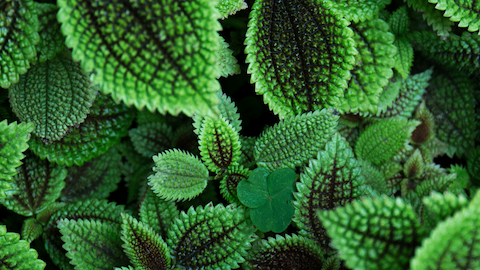
If you wanted a stage to be oval in shape, you could create a mask that defines that shape.

With that image applied as a mask to the stage, the visible area of the stage is clipped by the mask.
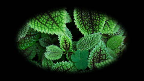
It’s important to understand that the black area in this image isn’t the mask being shown, it’s the backdrop. If you place another image on another stage set to a lower layer, that image will be shown everywhere that the top layer is masked.

QLab does not have an integrated mask editor. Instead, it watches the mask image file to look for changes; when it sees that the file has changed, it automatically reloads it. Thus, you can use any graphics editing program to make adjustments to a mask, and see changes applied live as you go.
To remove a mask, click the button to the right.
The Layout Tab
The Layout tab of the video stage editor allows you to define and arrange the stage’s regions. The stages which QLab automatically creates use a have a single region covering the whole stage.
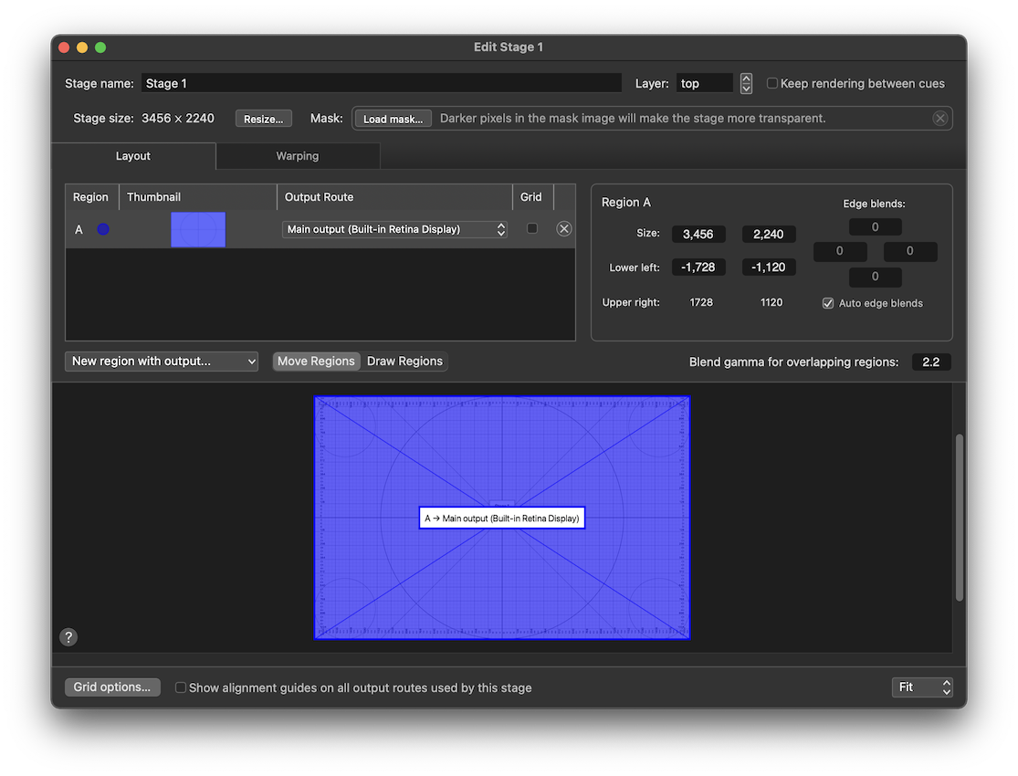
We’ll walk thorough the controls in the Layout tab first, and then go into more detail about regions and when you’d want to use more than one of them after.
The Region List
In the upper left part of the Layout tab is a table showing the regions of the stage. The table has five columns.
- Each Region are automatically assigned a letter index and a color;
Aand dark blue, in this screen shot. - A thumbnail, or miniature version of the region, can help you keep track of what’s what on stages that use several regions.
- The output route pop-up menu lets you tell QLab which output route the region should be sent to.
- The grid checkbox displays a monochrome alignment grid on the region. The grid has a few configuration options which are discussed below.
- The button deletes the region.
Underneath the list is a drop-down menu which lets you quickly create a new region using a specific output route. Next to that menu is a switch with two states. When the switch is set to Move Regions, you can use your cursor to move and resize existing regions in the canvas below. When the switch is set to Draw Regions, you can use your cursor to draw a new region in the canvas. Drawn regions will need to be assigned to an output route using the menu in the region list.
Region Parameters
The upper right part of the Layout tab shows several parameters of the region that’s selected in the list.
- Size shows the width and height of the region, and lets you edit the size by either typing in new values or clicking and dragging the cursor up or down. Regions cannot extend outside of the stage boundaries, so these text fields are limited based on the size of the stage and the position of the region.
- Lower left shows the coordinates of the lower left corner of the region compared to the center of the stage. The region can be positioned precisely by typing in new values or clicking and dragging up or down. Regions cannot extend outside of the stage boundaries, so these text fields are limited based on the size of the stage and the position of the region.
- Upper right shows the coordinates of the upper right corner of the region compares to the center of the stage. These values are not editable and are for reference only.
- The Edge blend text fields and checkboxes work together to define the amount of feathering, or fall-off, of each side of the region. Edge blending is best understood in the context of a stage with multiple regions (see below), but you can also use edge blends to soften the edges of a single-region stage.
Underneath these parameters is a text box which lets you set the gamma, or brightness curve, of all the edge blends in the current stage.
The Canvas
The canvas view is a white rectangle with black gridlines which represents the stage. Regions are drawn as colored rectangles labeled with their name and assigned output. When the Move Regions/Draw Regions switch is set to Move Regions, you can click on drag on an edge of a region to resize it, or in the center of the region to move it. The sides, vertical centerline, and horizontal centerline of the canvas are “magnetic,” so if you drag the edge of a region close by, it will snap to fit exactly. Edges of regions are also magnetic, making it easy to snap regions together and ensure that there is no accidental gap or overlap. You can hold down the command (⌘) key to disable snapping.
You can also adjust the selected region using the keyboard:
- Arrow keys move the selected region by one pixel.
- ⇧ + arrow keys move the selected region by ten pixels.
- ⌥ + arrow keys resize the selected region by one pixel.
- ⌥⇧ + arrow keys resize the selected region by ten pixels.
The selected region is drawn darker than unselected regions. Regions that have no output route assigned are drawn with dotted outlines.
Regions that use edge blends will draw the blend area with a hatched background.
By default, the canvas is scaled to fit the available space in the window, so enlarging the window will let you see the canvas in more detail. You can use the pop-up menu in the lower right corner of the window to set a particular scale factor if you prefer.
The Grid options… button displays a popover which allows to show all grids, hide all grids, and export a PNG image of the grid. It also allows you to switch between a white-on-black grid and a black-on-white grid, and optionally disable edge-blending between regions while the grid is showing. These options all exist in service of making it easier to configure the stage under a variety of conditions.
The checkbox labeled Show alignment guides on all output routes used by this stage displays a colored border, centerlines, and text labels on every output route that any region of the stage is assigned to use. Alignment guides always demonstrate the full raster of each route, without any warping, cropping, or other modification. The purpose of the alignment guides is to both positively identify each output route and its associated device, and to aid in the physical alignment and setup of the devices.
Understanding Regions
So, what are regions really and why does QLab have them?
The first and simplest answer is that regions are how a screen or projector (or NDI or Syphon output) knows which pixels of a stage to display. If you’re only using a single screen, regions feel like an unnecessary step. They can be easier to understand if you look at a stage that uses multiple screens.
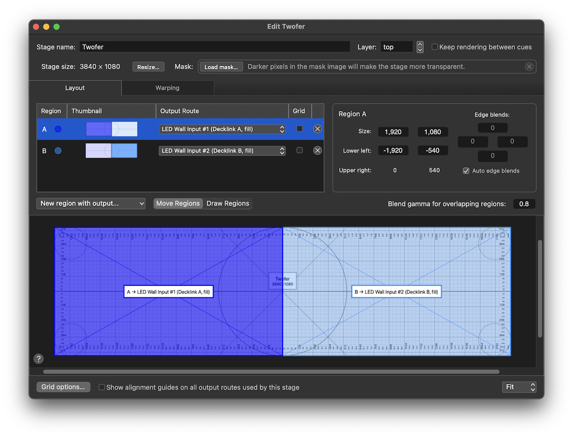
This stage is 3840 pixels wide by 1080 pixels tall; the size of two FHD2 rasters next to each other. If we imagine a situation in which two FHD2 projectors are perfectly aligned side by side and both projecting on, say, the cyclorama at the upstage edge of a traditional theater, it’s easier to see what regions do for us. Region A uses the output route for the house left projector and covers the camera left half of the stage, and region B uses the output route for the house right projector and covers the camera right half of the stage.
If you have two projectors laid out like this, though, the more common way to use them is to overlap their coverage a little bit at the center, and blend their edges together. This creates a very nice, seamless transition between the two projectors.
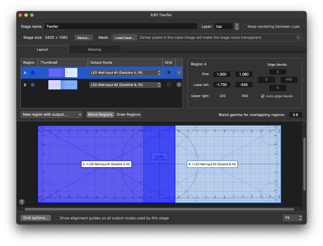
This stage is 3400 pixels wide by 1080 pixels tall. By overlapping regions A and B by the same amount as the actual projector beams are overlapped, you can create a single, seamless image across both projectors. The crosshatching in the center notates the area of each region that is blended. In this area, the same pixels from the stage are sent to both projectors, and QLab automatically calculates a soft dissolve across that area, fading the image for each projector so that the overall brightness of the stage remains constant.
You can manually adjust the size of the blend region by unchecking the Auto edge blends box, and you can adjust the brightness curve of the blend by using the Blend gamma control.
Regions can also be used to subdivide a stage into sections that need to be individually controlled.
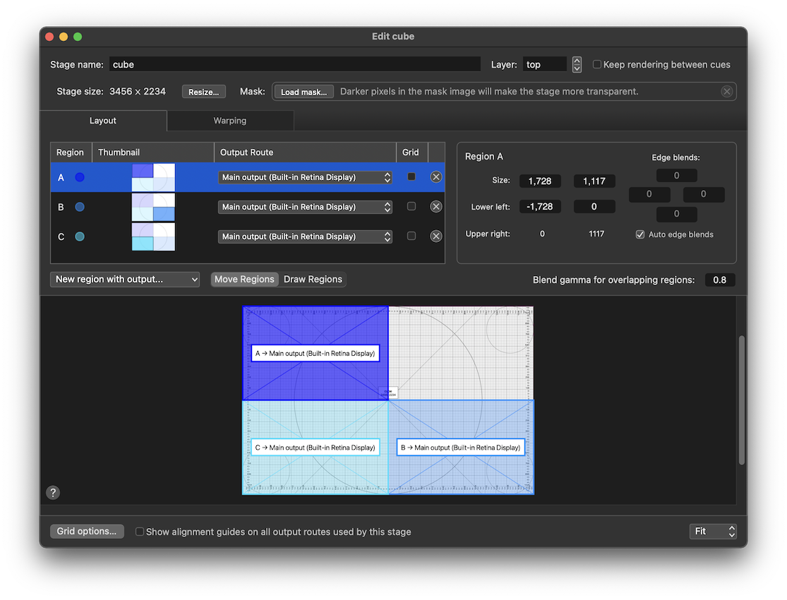
Here, three of the quadrants of a stage are covered by three regions. Each of those regions uses the same output route, and therefore the same screen. Each of those three regions can be individually positioned within the raster of the output, and individually warped as we’ll discuss in the next section.
The Warping Tab
The Warping tab has the same basic form as the Layout tab and an identical region list, but it displays different parameters of the selected region, and gives you different things to adjust in the canvas.
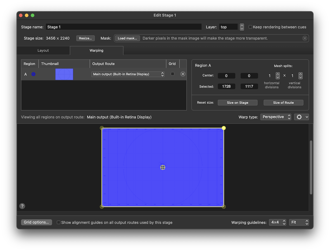
The purpose of the Warping Tab is to let you adjust the geometry of the stage on a per-region basis. Regions can be warped for any number of reasons, the most straightforward of which is to correct for keystoning caused by an off-axis projector. Warping can also be used to match a video projection to a non-flat projection surface, or for other creative effects.
Region Parameters
The upper right part of the Warping tab shows several other parameters of the region that’s selected in the list.
- Center shows the coordinates of the center of the region compared to the center of the stage. When a region is warped, as will be discussed below, it can be difficult to mathematically define the true center of the region. Therefore, in this view only, “center” really means the functional center of the region, and not necessarily the exact actual center. You can edit these values by typing new ones in or by clicking and dragging up or down.
- Selected shows the coordinates of the currently selected control point below. You can edit these values by typing new ones in or by clicking and dragging up or down.
- Mesh splits are a pair of up/down arrow buttons which let you increase or decrease the number of controls points used to warp the selected region. Each control can be adjusted from 1 up to 32 using powers of two.
Below the editable attributes are two buttons which reset the selected region. You can use these to start over if you’ve tangled yourself up.
- Size on Stage resets both mesh splits to 1 and sets the region to match the size of region defined in the Layout tab.
- Size of Route resets both mesh splits to 1 and sets the region to match the size of the output route that it’s assigned to use.
The Canvas
In the Warping tab, the canvas looks different depending on which region is selected. The grey rectangle with the thin, purple-ish border represents the output route that the selected region is assigned to use. Every region of the stage that’s assigned to use that output route is drawn in color. The selected region is drawn with a yellow border.
By default, the output route is drawn with a 4 × 4 grid of warping guidelines. These lines never appear in QLab’s output, they’re only visible here to aid with warping and alignment. You can change their layout using the pop-up menu in the lower right corner of the window next to the scale pop-up menu. The edges of the output route and the guidelines are all “magnetic”, so control points snap to them.
Regions can be adjusted in a great number of ways here. Holding down the shift (⇧) key while doing any of these adjustments allows fine-tuning. Holding down the command (⌘) key while doing any of these adjustments temporarily disables snapping.
- Click and drag on a control point (which is drawn as either a circle or diamond for reasons discussed below) to warp the region using that control point.
- Click and drag on a control point while holding down the option (⌥) key to move the whole region using that control point as the reference.
- Place your cursor within the region where it displays as a hand, then click and drag to move the whole region.
- Place your cursor on an edge of the region where it displays as a line with a bidirectional arrow, then click and drag to warp the region by moving the whole edge.
- Place your cursor just inside an edge of the region where it display as a line with an inwards-pointing arrow, then click and drag to warp the region along a single axis only by moving the whole edge.
You can also use keyboard shortcuts to navigate between control points and adjust them:
- W, A, S, and D keys move the selection between control points, selecting the point that is above, to the left, below, or to the right of the currently selected point.
- Arrow keys move the selected control point by one pixel.
- ⇧ + arrow keys move the selected control point by ten pixels.
The Warp Type pop-up menu, which applies to all regions that share an output route, lets you choose the geometric approach that QLab uses to warp the regions on that route.
Perspective warping, which is the default type, is the most generally applicable.
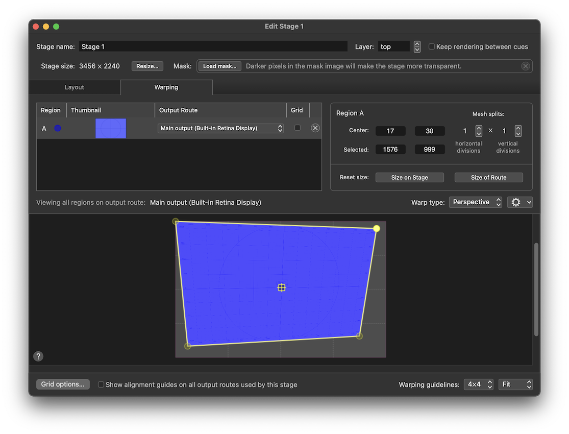
Using perspective warping, a projected object will appear the same size no matter where it’s placed on the region. However, in order to allow complex perspective warped shapes, QLab uses “continuous perspective” warping which guarantees continuity of the warp, but means that extreme warps might not be truly 100% perspective-correct.
Linear warping is a more direct, mathematically straightforward warp.
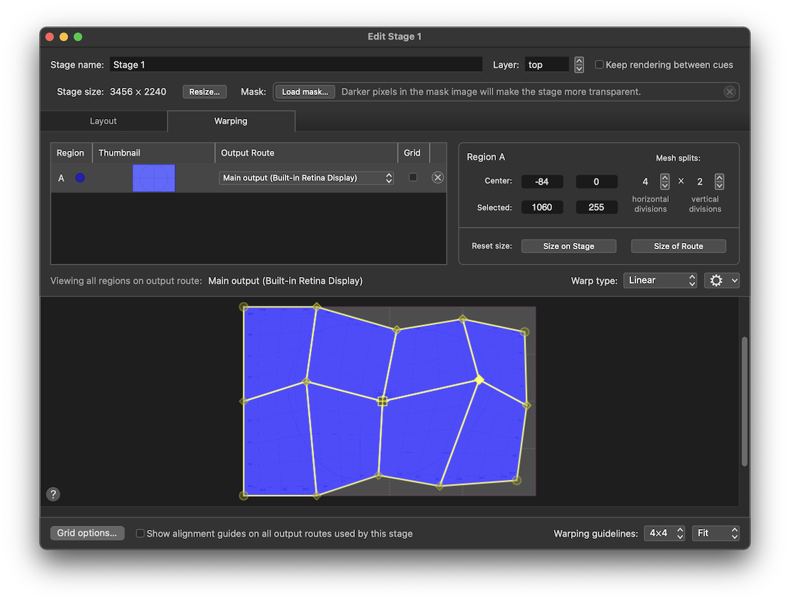
This type might look better with very complex, multi-faceted warps, but will typically look odd at extreme angles.
Bézier warping is a more complex type, used to project onto curved surfaces.
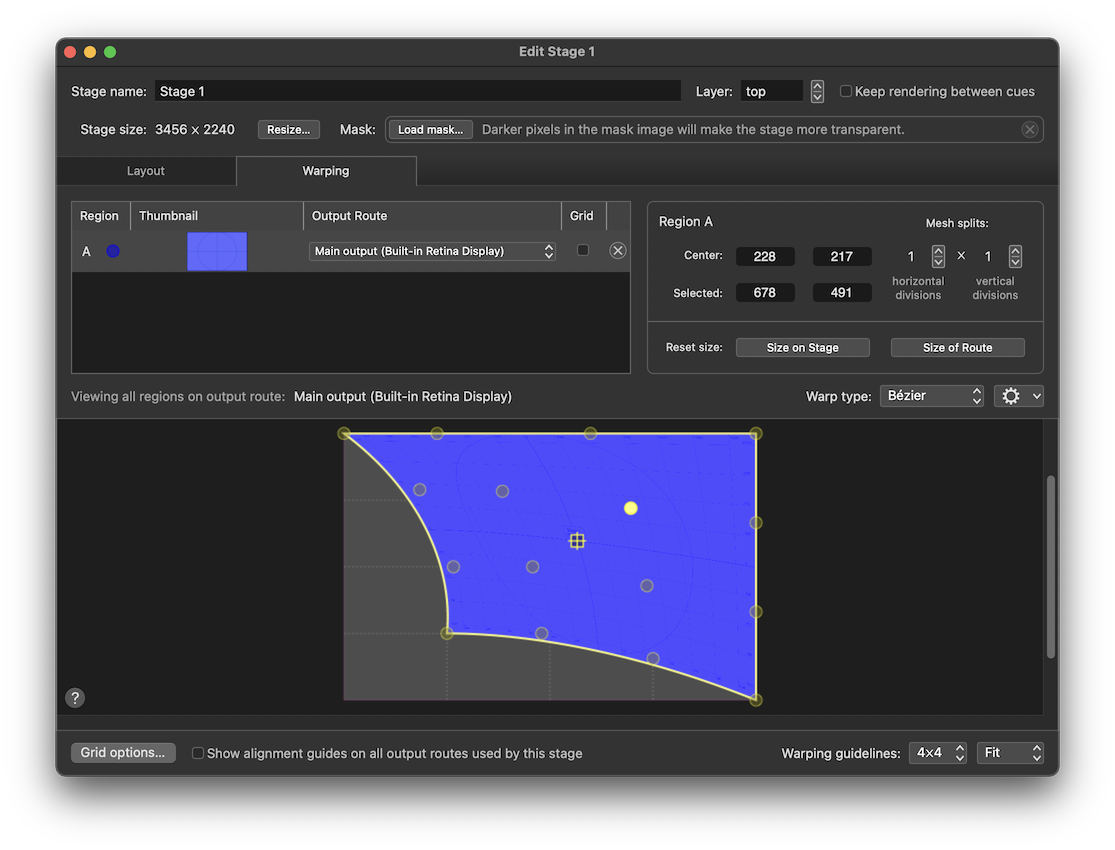
This warp type gives you sixteen control points per mesh split, and each control point bends the warp smoothly in the direction that it’s pulled, as though the region is made of an elastic material.
The menu contains two menu items which are relevant to a very specific situation: when control points of two or more regions are overlapping precisely. When they are, this menu can be used to link those control points together so that they move as one, or unlink them to move them independently.
When control points are linked, they are drawn as a diamond instead of a circle. Linked, diamond-shaped control points behave just like round ones except that moving them changes the region that each linked point belongs to simultaneously.
Using the region example above with three regions assigned to a stage, all using the same output route, we get a nice example of linking control points.
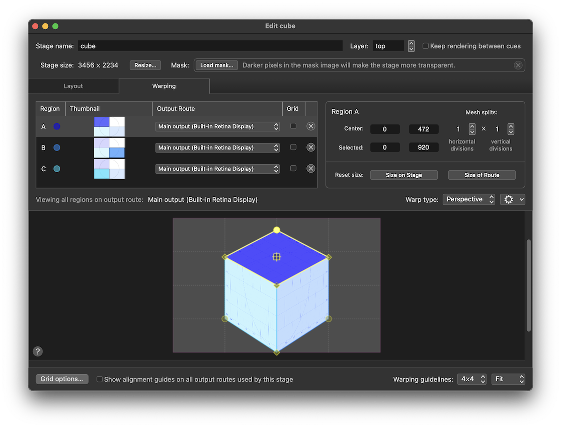
Imagine the output route is connected to a projector that is pointing at a cube-shaped object on stage. Here, the three regions are each warped to conform to a single face of the cube, and the control points on each region that coincide with controls points on other regions are linked. This allows you to warp the regions to fit the cube as a single object, instead of three separate objects.
Output Routes
Output routes connect QLab to video output devices.
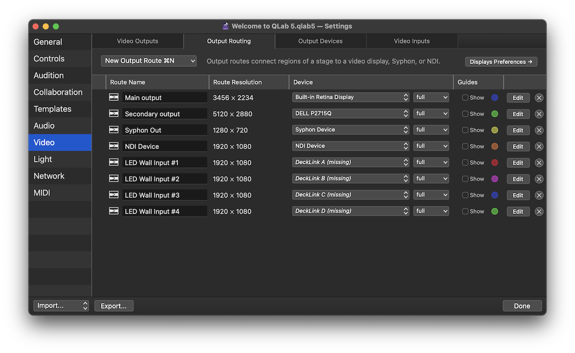
This workspace contains eight output routes of various types. The output routes in the workspace are listed in a table with several columns.
- The Route Name column lets you see and edit the name of the route. Note that if you plan to use OSC to control a route by name, you must give the route an OSC-compatible name, i.e. one without spaces or special characters reserved by the OSC spec.
- The Route Resolution column shows the pixel dimensions of the route.
- The Device column contains two pop-up menus which let you see and change which device the route uses, and how that device is used. These menus are discussed below. When a route was configured using a device which is not currently available, like the last four routes in the screen shot above, the device name is displayed in italics and appended with the word (missing).
- The Guides column contains checkboxes which let you display a colored alignment guide for each route. When the checkbox is checked, QLab displays a colored outline, centerlines, circular corner and center registration marks, and the route name on the full raster of the output. These guides, which are not affected by region warping, can be used to identify and physically align video devices.
- The Edit button opens the route editor, which allows you to change the properties of the route. The route editor is discussed below.
- The button deletes the route, which is an undo-able operation.
To create a new output route, click the New Output Route button. When the Output Routing tab is open and frontmost, the keyboard shortcut ⌘N (which ordinarily creates a new workspace) is a shortcut for this button. The button opens a pop-up menu to allow you to create a new route with some initial settings if you so choose.
- New output route with device: - select a device to create a new output route using the selected output device, with the route configured according to the properties of that device.
- New NDI output route… - this option prompts you to enter the configuration details for a new NDI device, then creates that device and an output route using it.
- New Syphon output route… - this option prompts you to enter the configuration details for a new Syphon device, then creates that device and an output route using it.
- New output route with partial screen device: - this option is discussed below.
The Output Route Editor
Clicking the Edit button next to a route opens the output route editor.
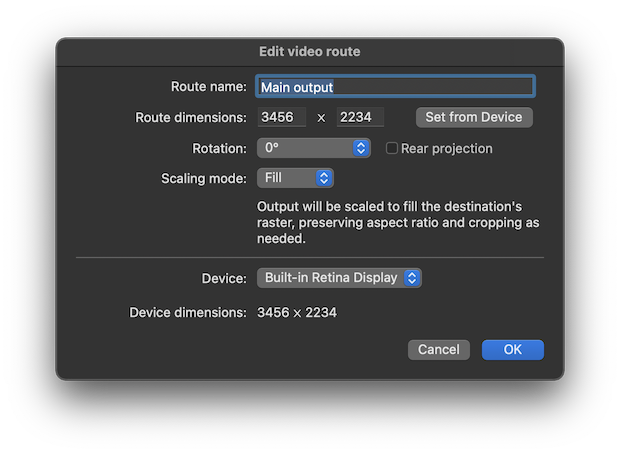
Route name can be any name you choose, and is a name which matters more to humans than to the computer.
Route dimensions can be anywhere from 1 × 1 pixels to 30,000 × 30,000 pixels. The Set from Device button sets the route dimensions to match the dimensions of the assigned device.
Rotation lets you rotate the output raster in 90° increments. The Rear projection checkbox mirrors the output horizontally to correct for rear projection.
Scaling mode tells the route how to behave if the route dimensions and the device dimensions do not perfectly match.
- Center will align the centers of the route and the device, and display the route at its original pixel density. If the route is larger, the edges of the route will be cut off. If the device is larger, the route will display black around the edges.
- Fit will scale the route to fit the device while maintaining the original aspect ratio of the route, adding black fill where necessary.
- Stretch will scale the route to fit the device exactly, scaling the width and height independently.
- Fill will scale the route to fit the device exactly, but instead of stretching the route if it doesn’t fit perfectly, it will crop either the width or height.
Device gives you another place to select the device being used by the route. The dimensions of the selected device are displayed right below.
Using scaling modes
Scaling mode mainly only comes into play if you ever need to use an existing route with a new video device of a different resolution. One example of this situation is a touring show which carries its own Mac and QLab workspace, but uses whatever video projector each venue has available.
Imagine a workspace that was created using a projector with a resolution of 1920 × 1080 and then brought on tour. Perhaps one tour stop has a 1920 × 1200 projector, another has a 1280 × 720 projector, and a third has a 3840 × 2160 projector.
When setting up at each venue, you’d connect the house projector to your Mac, open QLab, visit Workspace Settings → Video → Output Routing, select the output route for your stage, and using the menu in the Device column to configure the route to use the new projector.
The way your stage appears on the projector will be determined using the scaling mode of the route. Experimenting with the four modes will help you learn how each behaves and which one best matches your technical and aesthetic needs.
Partial Outputs
Display splitters such as the Matrox DualHead2Go, TripleHead2Go, and QuadHead2Go, the Datapath Fx4 and Hx4, and the AJA HA5-4K appear to macOS as a single, very large display. You then connect two, three, or four displays to the output of the splitter, and the splitter provides one half, one third, or one quarter of the pixels of its input to each output.
These devices can be configured to present as a wide display sliced into side-by-side sections, a tall display sliced into top-to-bottom sections, or a large display slice into rows and columns.
To give you the greatest amount of control when working with devices like these, you can configure an output route to use only a specific portion of an output device and behave as though that portion is a whole device. In this way, QLab can be made to behave the way the splitter is behaving.
Output Devices
Output devices are QLab’s representation of the actual devices that video is displayed upon. Those devices can be:
- Monitors, televisions, screens, and projectors directly connected to your Mac.
- Any Blackmagic Design UltraStudio, Intensity, and DeckLink devices with output capabilities.
- NDI network video outputs.
- Syphon server video outputs.
Devices available to the workspace are listed in a table with several columns.
- The name columns shows the name of the device. For most hardware devices, this name is set by the manufacturer and not editable. NDI and Syphon device names are editable and can be set to any name of your choosing.
- The resolution column shows the pixel dimensions of the device.
- The info column shows any other available information. For many devices, this is simply the frame rate (refresh rate) of the device. For NDI devices with audio output configured, audio channel information is also shown.
- The Edit button next to Blackmagic Design, NDI, and Syphon devices allows you to edit the properties of those outputs.
- The button next to NDI and Syphon devices deletes the device, which is an undo-able operation.
Blackmagic Design Outputs
Blackmagic Design makes a number of video input and output devices across a fairly wide range of prices and capabilities. Some of these devices have inputs only, and naturally those will not appear amongst the list of available output devices. Others have anywhere from one to eight outputs.
Blackmagic devices which have multiple outputs will appear a separate devices in the Output Devices list. For example, the DeckLink Duo, which is a PCIe card, is really two two-channel video interfaces built into a single card. If all four channels are configured as outputs, they will each appear as a separate device.
Clicking the Edit… button will allow you to edit the Blackmagic device’s settings. The available settings and options vary based on the exact type of device, but they are all generally similar.
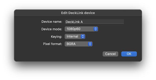
Device name
This name is read-only in QLab. You can change the device name in the About section in the Blackmagic Desktop Video Setup app. QLab must be restarted to recognize a name change.
Device mode
This menu lets you select the resolution and frame rate mode for output. The available modes vary based upon the device. This setting is also available in the Blackmagic Desktop Video Setup app. QLab’s setting here is a sort of remote-control for the setting in that app.
Keying
Some Blackmagic devices offer internal and external alpha keying, and QLab 5 supports keying on these devices. Alpha keying relies on transparency, or alpha, in the source image. If your source image uses a green or blue background, such as a Camera cue showing a performer in front of a green or blue screen, you can use a linear key video effect to convert the solid color background into a transparent background.
The Keying pop-up menu lets you choose between None, which is the default, External keying, or Internal keying.
Choosing Internal or External Keying
External keying uses two physical outputs on the device to output a pair of video signals called the “key” and the “fill” which can be sent to another video device such as a vision mixer. The vision mixer can then overlay the fill signal on top of another video source, using the key to “cut” out the parts of the fill that are supposed to be transparent. The Blackmagic device maintains frame-accurate synchronization between these two outputs.
If you are using a desktop or rackmount device, the two outputs in question are usually a pair of SDI connectors labeled “A” and “B”. If you are using PCIe card device, you’ll need to manually configure the card to use two SDI connectors for a single output. This is done in the Connectors section of the Blackmagic Desktop Video Setup app.
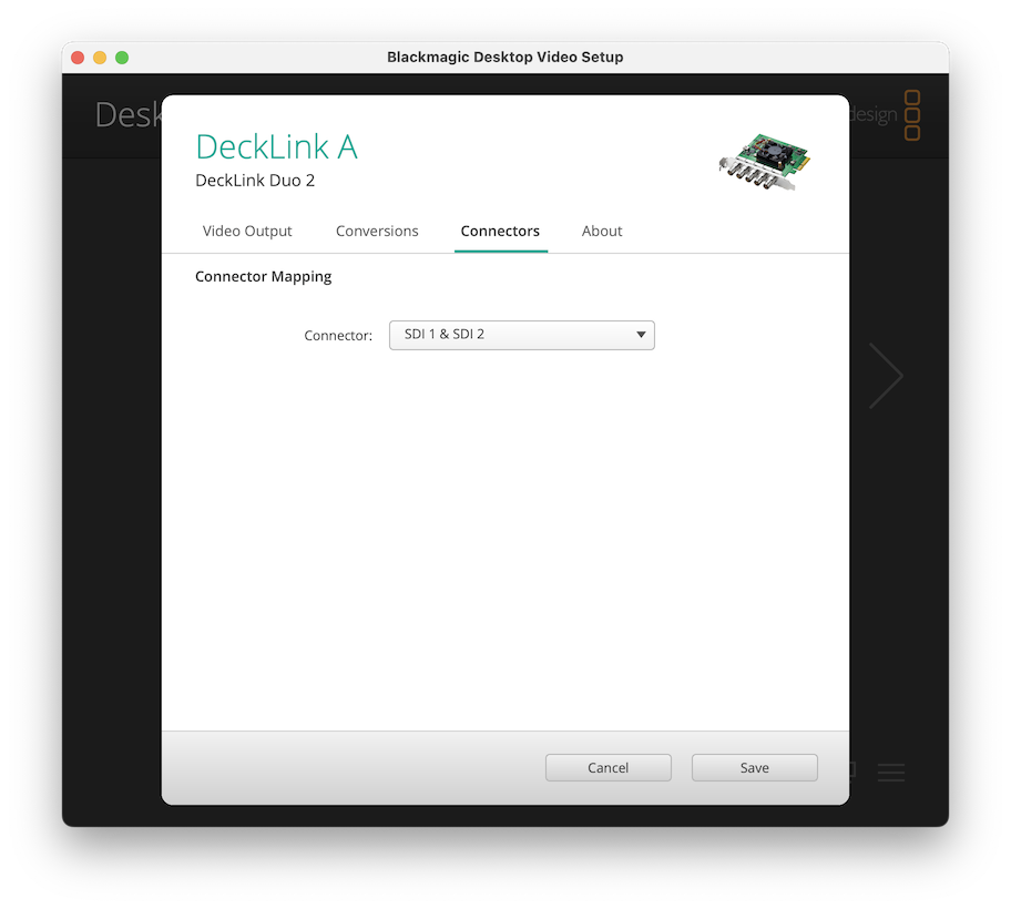
Using external keying requires hardware downstream of your QLab system to be able to take in and make use of a key/fill pair. Otherwise, the key signal will simply look like a greyscale version of the fill signal, and the fill signal will simply look like itself, but with any transparency replaced with opaque black.
Internal keying allows you to overlay the output of QLab on top of a separate live input to the Blackmagic device. This compositing is done inside the Blackmagic hardware and is extremely low-latency, so if you are using QLab to overlay graphics on top of a live video signal, you may prefer the visual results of routing the live signal through the Blackmagic device (and not through a Camera cue), and then using internal keying to superimpose your graphics.
Using internal keying requires an input signal to the Blackmagic device that does not pass through QLab. Otherwise, there’s nothing to combine with and the output will look the same as it would if you set the keying mode to “none.”
Many Blackmagic devices which support internal keying require all inputs and outputs involved to use the exact same resolution and frame rate. If you are having problems with internal keying, this is the best first thing to check.
Pixel format
Most Blackmagic devices allow you to choose between two video output formats: BGRA and Y’CbCr. Whole books could be written about these two color models, so this manual will offer a few brief details and leave further research to the curious reader.
- BGRA offers the best theoretical picture quality, although its superiority may not be visible in many practical applications.
- BGRA must be used if you are using either of the optional keying modes detailed above.
- Y’CbCr may be required when using some resolutions above 1920 × 1080 or frame rates above 60 Hz.
- Y’CbCr may be required when connecting directly to some broadcast video equipment.
The guiding principle is this: if you are using a Blackmagic device which supports both BGRA and Y’CbCr formats, and your picture looks wrong, try changing this setting. If it looks right, it is right.
NDI Outputs
NDI outputs are virtual devices, and therefore do not have an inherent resolution, frame rate, or name. The Edit button opens the NDI device editor to allow you to configure those properties.
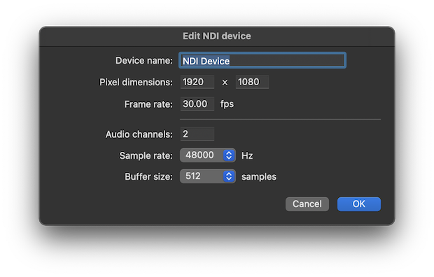
When a Video or Camera cue is assigned to a stage that uses an NDI device for output, that cue’s audio output can use the audio portion of the NDI device if you like, but does not need to.
In order to remain predictable to external equipment, once a workspace starts sending video to an NDI output, QLab will keep that NDI output active until the workspace is closed, even if the workspace is panicked or hardStopped.
Syphon Outputs
Syphon outputs are also virtual devices, similarly editable.
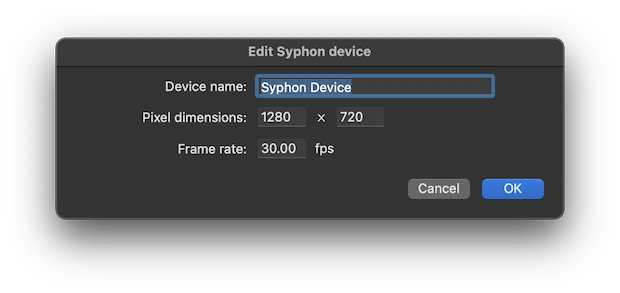
In order to remain predictable to external equipment, once a workspace starts sending video to a Syphon output, QLab will keep that Syphon output active until the workspace is closed, even if the workspace is panicked or hardStopped.
Video Signal Flow Examples
There are several stages in QLab’s video pipeline, each of which can modify an image in its own ways.
In brief, as discussed in the Introduction To Video In QLab, the video signal path in QLab does like this:
Source → Cue → Stage → Region → Route → Device.
For Video cues, the source is a moving or still image file stored on your Mac. For Camera cues, the source is a video input patch which brings images in from a camera or other external source of live video. For Text cues, the source is the text entered in the Text tab of the inspector for the cue which is then rendered as a PNG image internally by QLab.
For these examples, we’ll use a Video cue targeting a still image and set to fill stage mode. We could use a moving image target or another type of video-related cue and get the same results, of course, but this straightforward source cue helps make the examples clear. The cue is assigned to a stage named “Upstage Center”.
These examples also use Syphon to simulate a video projector. This lets us use the Simple Client, a very straightforward Syphon display app, to make nice screen shots of the output instead of setting up an actual projector, pointing it at an actual wall, and taking photographs.

Example 1: one-to-one
If we’re using a single projector for this stage, and pointing that projector at a single flat surface like a wall, screen, or cyclorama, our needs might be very simple: just display the whole cue without doing much to it.
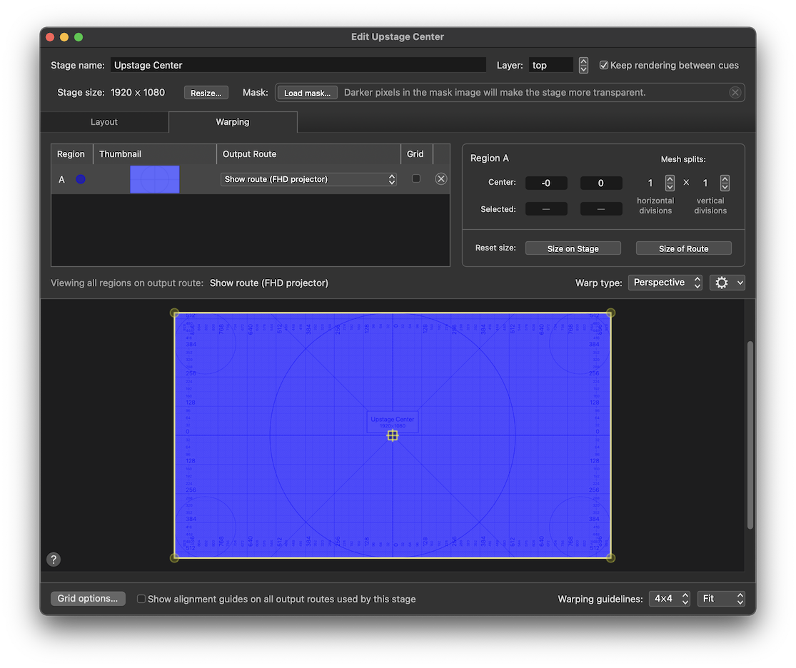
To achieve this, the stage has a single region which covers the whole stage in the Layout tab of the stage editor:
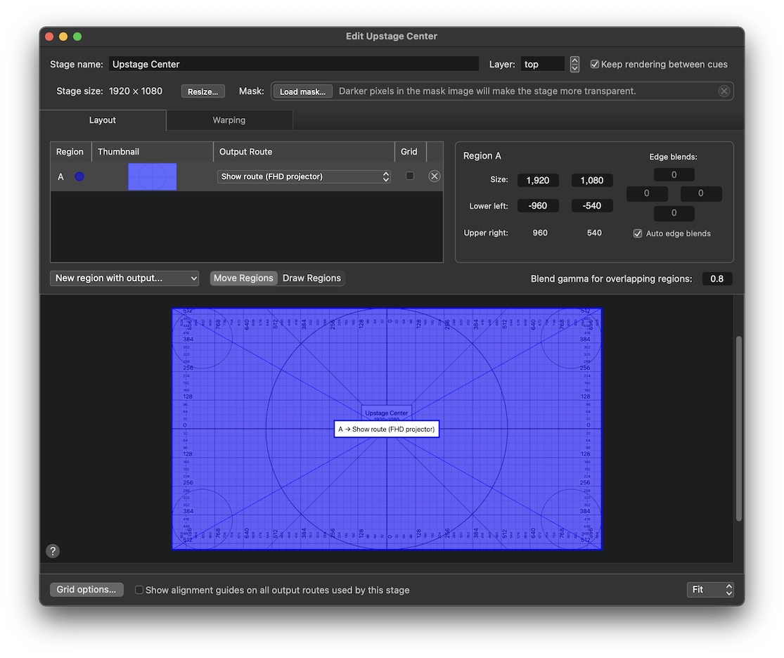
That region also fills the whole output route in the Warping tab of the stage editor:
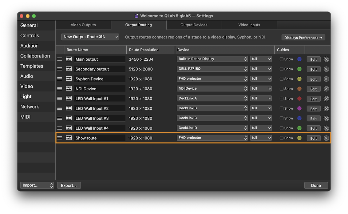
The route is configured to use the full raster of its assigned output device:
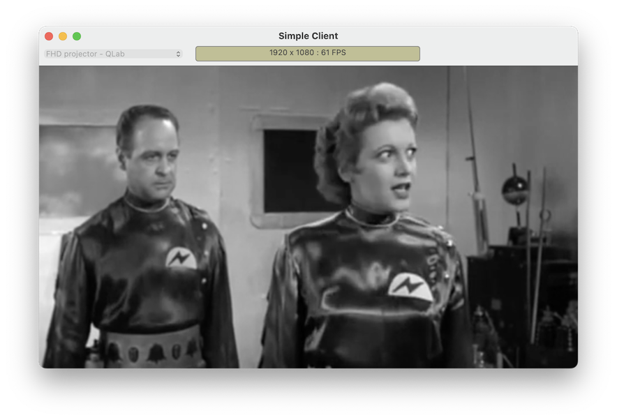
The result is that every pixel of the device is utilized to display every pixel of the cue. Since the stage, route, and device all have a resolution of 1920 × 1080, there is a straight one-to-one correspondence between the cue’s pixels and the device’s pixels.
Example 2: right half
Perhaps the left half of the projector beam is hitting scenery which we don’t want to project upon, but we want the right half to be left exactly as it was.
To achieve this, the region only covers the right half of the stage in the Layout tab of the stage editor:
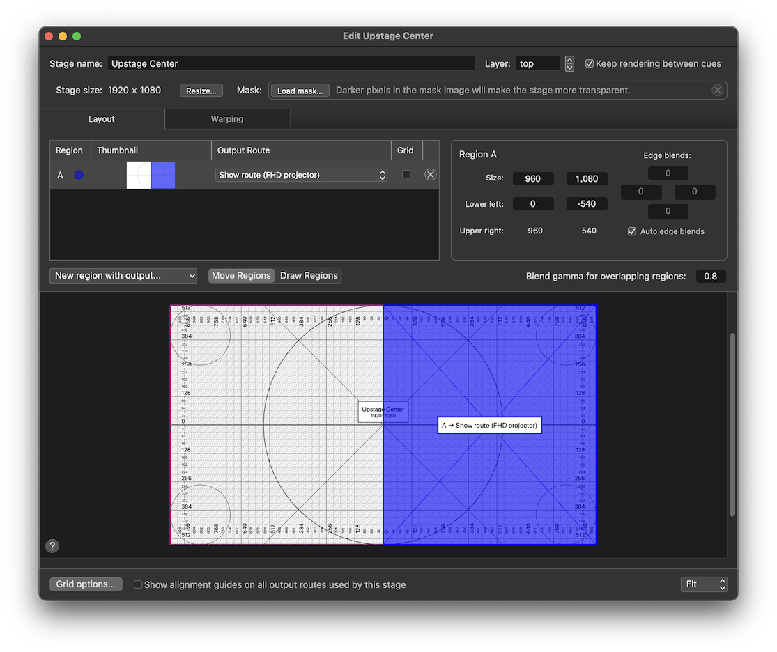
The region similarly covers only the right half of the route in the Warping tab:
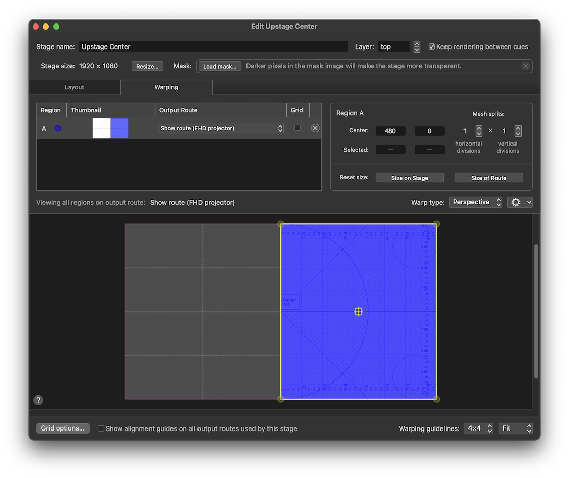
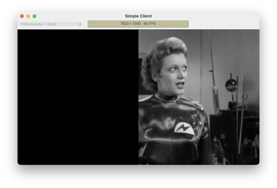
The result is that the right half of the cue is displayed using the right half of the device.
Example 3: right half reversed
What if we want to use the right half of the source image, just like in example 2, but we want to display it on the opposite side of the screen?
To achieve this, the Layout tab looks the same:

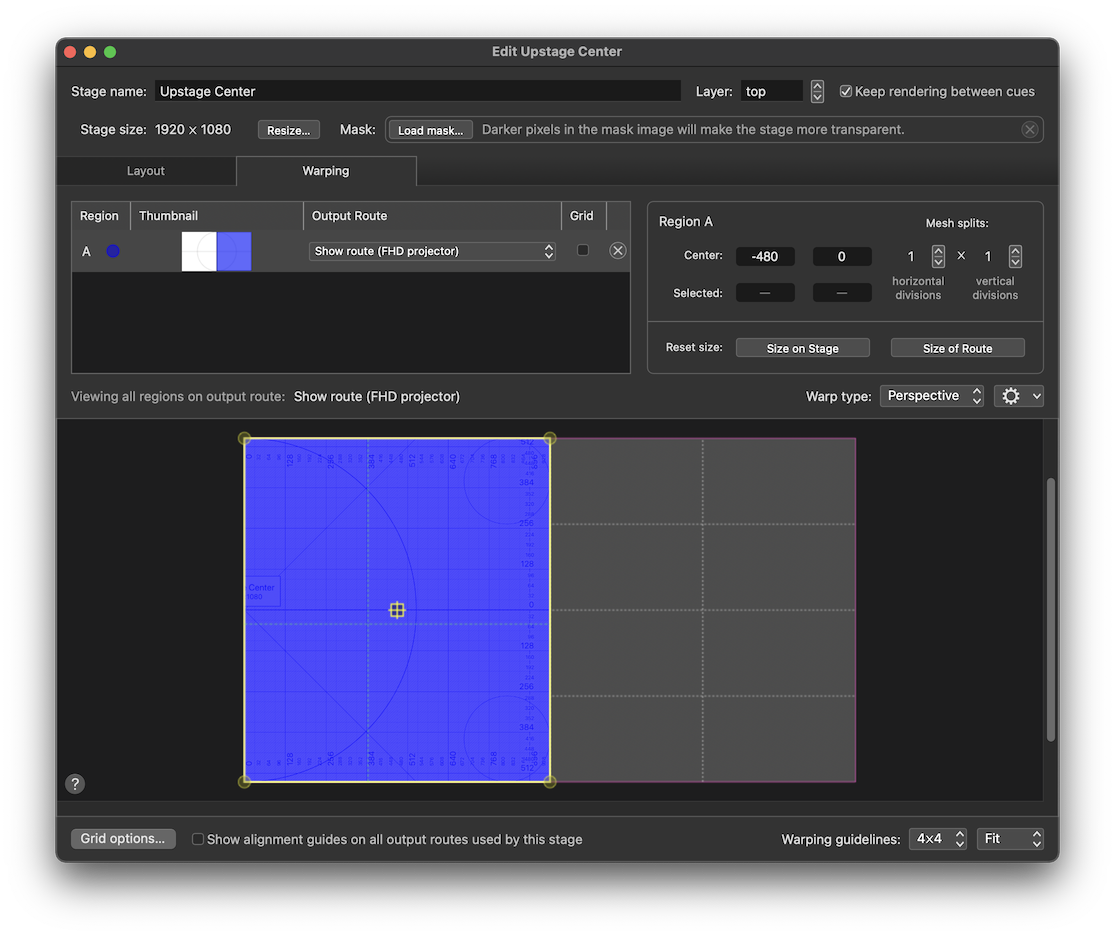
But in the Warping tab, we move the region to the left half of the route:
The route stays the same:

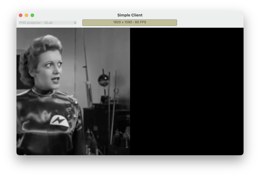
The result is that the right half of the cue is displayed using the left half of the device.
- Raster originally meant the grid of dots in a television which produced a visible image. It now refers to the pattern of pixels which represent a digital image, both as encoded data within the computer and as a physical collection of pixels in a display device like a monitor or projector.↩
- Full High Definition, or 1920 × 1080 pixels.↩
Still have a question?
Our support team is always happy to help.